
Product Manual B
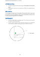
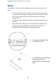
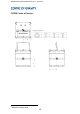

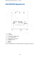
Table Of Contents
- INTRODUCTION
- DESCRIPTION
- IDENTIFICATION MARKS
- SIGN-OFF FORM
- UNIT SPECIFICATION
- SAFETY
- ACCESS AND SECURITY
- CENTRE OF GRAVITY
- CAB OVERVIEW (Standard Unit)
- LIFTING
- FILLING THE FCP
- DISPENSING FUEL
- TRANSPORTING
- STRAPPING CHARTS
- MAINTENANCE AND SERVICE SCHEDULE
- RECOMMENDED INSPECTION - MAINTENANCE
- ENVIRONMENTAL RESPONSIBILITY
- SPILLS
- CONTAINMENT
- DISPOSAL
- TROUBLE SHOOTING
- WARRANTY

WM006 FCP250-500-1000-EN Revision 1 - Sep 2019
12
Venting
Each unit has 2 common vents installed; these are in the Cab Area of the
tank.
• 2” Pressure Vacuum Vent – Allows movement of air into the unit
at low pressure during the pumping process and allows air out of
the unit at a higher pressure to stop an over pressure of the
internal tank
• ¼” Roll over Vent – Allows free flow air into and out of the tank at
all times.
• Please follow local regional, state and national Fire Safety Codes
and other governing Installation Codes for the Normal and
Emergency Venting equipment and appurtenances.
1. 2” Pressure / Vacuum Vent
2. ¼” Roll Over Vent
3. The FCP1800 has an additional
emergency vent port
postionoed to the rear of the
unit