WTI Part No. 13532 Rev.
Warnings and Cautions: Installation Instructions Secure Racking If Secure Racked units are installed in a closed or multi-unit rack assembly, they may require further evaluation by Certification Agencies. The following items must be considered. 1. The ambient within the rack may be greater than room ambient. Installation should be such that the amount of air flow required for safe operation is not compromised. The maximum temperature for the equipment in this environment is 55°C.
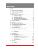
Table of Contents 1. Introduction. . . . . . . . . . . . . . . . . . . . . . . . . . . . . . . . . . . . . . . . . . . . . . . . . . . . . . . . . . . . . 1-1 2. Unit Description. . . . . . . . . . . . . . . . . . . . . . . . . . . . . . . . . . . . . . . . . . . . . . . . . . . . . . . . . . 2-1 2.1. Front Panel Components - RPC-4850 Series . . . . . . . . . . . . . . . . . . . . . . . . . . . . . . . . . 2-1 2.2. Back Panel Components - RPC-4850 Series. . . . . . . . . . . . . . . . . . . . . . . . . .
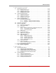
Table of Contents 5. Basic Configuration (continued) 5.5. Managing User Accounts. . . . . . . . . . . . . . . . . . . . . . . . . . . . . . . . . . . . . . . . . . . . . . . . 5-19 5.5.1. Viewing User Accounts. . . . . . . . . . . . . . . . . . . . . . . . . . . . . . . . . . . . . . . . . . . 5-19 5.5.2. Adding User Accounts. . . . . . . . . . . . . . . . . . . . . . . . . . . . . . . . . . . . . . . . . . . 5-19 5.5.3. Modifying User Accounts. . . . . . . . . . . . . . . . . . . . . . . . . . . .
Table of Contents 7. Alarm Configuration. . . . . . . . . . . . . . . . . . . . . . . . . . . . . . . . . . . . . . . . . . . . . . . . . . . . . . 7-1 7.1. The Over Temperature Alarms. . . . . . . . . . . . . . . . . . . . . . . . . . . . . . . . . . . . . . . . . . . . . 7-2 7.1.1. Over Temperature Alarms - Load Shedding and Auto Recovery . . . . . . . . . . . 7-4 7.2. The Circuit Breaker Open Alarm (RPC-40L8A4 Series Units Only). . . . . . . . . . . . . . . . . 7-5 7.3.
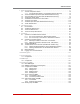
Table of Contents 14. Setting Up SSL Encryption. . . . . . . . . . . . . . . . . . . . . . . . . . . . . . . . . . . . . . . . . . . . . . . . 14-1 14.1. Creating a Self Signed Certificate . . . . . . . . . . . . . . . . . . . . . . . . . . . . . . . . . . . . . . . . . 14-2 14.2. Creating a Signed Certificate. . . . . . . . . . . . . . . . . . . . . . . . . . . . . . . . . . . . . . . . . . . . . 14-3 14.3. Downloading the Server Private Key. . . . . . . . . . . . . . . . . . . . . . . . . . . . . . . . .
Table of Contents List of Figures 2.1. 2.2. 2.3. 2.4. 3.1. 3.2. 3.3. 3.4. 4.1. 4.2. 5.1. 5.2. 14.1. B.1. B.2. Front Panel (Model RPC-4850-48V Shown). . . . . . . . . . . . . . . . . . . . . . . . . . . . . . . . . . . . . 2-1 Back Panel (Model RPC-4850-48V Shown). . . . . . . . . . . . . . . . . . . . . . . . . . . . . . . . . . . . . 2-2 Front Panel (Model RPC-40L8A4 Shown). . . . . . . . . . . . . . . . . . . . . . . . . . . . . . . . . . . . . . . 2-3 Back Panel (Model RPC-40L8A4 Shown). . . . . . . .
1. Introduction Electronic equipment sometimes "locks-up," requiring a service call just to flip the power switch to perform a simple reboot.
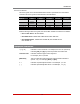
Introduction RPC Series Models: This user's guide covers several different RPC models. Specifications for the models covered in this user's guide are summarized in the table below: Input Feeds Input Voltage Max. Load per Outlet Max. Load per Input Max. Load per Unit RPC-4850-48V 2 ea, 50 Amp Redundant -18 to -72 VDC 15 Amps 50 Amps 50 Amps RPC-4850-24V 2 ea, 50 Amp Redundant 18 to 72 VDC 15 Amps 50 Amps 50 Amps RPC-40L8A4-48 2 ea, 40 Amp 18 to 72 VDC 10 Amps 40 Amps 2 @ 40 Amps ea.
2. Unit Description 2.1. Front Panel Components - RPC-4850 Series www.wti.com Remote Power Controller RPC-4850 CIRCUITS 1 2 1 3 4 5 6 CONTROL 7 8 2 RDY ON 3 Figure 2.1: Front Panel (Model RPC-4850-48V Shown) As shown in Figure 2.1, the RPC-4850 Series Front Panel includes the following: Circuit Status Indicators: A series of eight LED indicators, which light when power to the corresponding circuit is Switched On. RDY Indicator: Flashes when the RPC is ready to receive commands.
Unit Description 2 3 4 1 5 6 7 A 8 D B BUS A ACT 2 3 4 5 6 7 8 15 15 15 15 15 15 15 15 LINK 10/100BaseT CONSOLE RDY -48 CKT 1 Ø -48 CKT 2 Ø -48 Ø CKT 3 -48 Ø CKT 4 -48 CKT 5 Ø -48 CKT 6 Ø -48 CKT 7 Ø BUS B 50 Ø Ø DEF RST 1 -48 50 Ø -48 -48 CKT 8 C E Figure 2.2: Back Panel (Model RPC-4850-48V Shown) 2.2. Back Panel Components - RPC-4850 Series As shown in Figure 2.
Unit Description RPC ACT Remote Power Controller LINK ALARM INPUT OUTPUT STATUS DEFAULT ON Ethernet 10/100 RESET A1 RDY A2 A3 A4 B1 B2 B3 B4 1 2 3 4 PHONE 1 2 3 4 5 6 7 www.wti.com 8 Figure 2.3: Front Panel (Model RPC-40L8A4 Shown) 2.3. Front Panel Components - RPC-40L8A4 Series As shown in Figure 2.3, the RPC-40L8A4 Series Front Panel includes the following: Note: All Reset and Default button functions can also be disabled via the System Parameters menu, as described in Section 5.
Unit Description 1 2 4 6 3 5 7 Figure 2.4: Back Panel (Model RPC-40L8A4 Shown) 2.4. Back Panel Components - RPC-40L8A4 Series As shown in Figure 2.4, the RPC-40L8A4 Series Back Panel includes the following: Power Input: Two 40 Amp DC input Buses that share a common chassis ground line. The power input terminal block also includes two mounting brackets, which are used to hold the protective cover (not shown).
Unit Description 2.5. Additional Button Functions The Default and Reset buttons can be used to perform the functions described below: Notes: • All button functions can also be disabled via the System Parameters menu, as described in Section 5.3. • When the RPC is reset to factory defaults, all user-defined configuration parameters will be cleared, and the default “super” user account will also be restored. 1. 2. 3.
3. Getting Started This Quick Start Guide describes a simplified installation procedure for the RPC, which will allow you to communicate with the unit in order to demonstrate basic features and check for proper operation. Notes: • There are separate Hardware Installation procedures for RPC-4850 series units and RPC-40L8A4 series units. RPC-4850 series units are discussed in Section 3.1 and RPC-40L8A4 series units are discussed in Section 3.2.
Getting Started 3.2. Hardware Installation - RPC-40L8A4 Series Units 3.2.1. Apply Power to the RPC-40L8A4 Refer to power rating nameplate on the back panel, and then remove the protective cover from the terminal block and connect the RPC-40L8A4 unit to an appropriate power source as shown in Figure 3.1 below.
Getting Started 3.2.2. Connecting Switched Devices to the RPC-40L8A4 The output terminals on the RPC-40L8A4 back panel are used to connect DC voltage to each switched device. Each output terminal includes eight connectors (four circuits.) To connect wires to the DC output terminal block, refer to Figure 3.2 below and proceed as follows: Note: Each individual output circuit will support up to 10 Amps maximum; the total for all four circuits on either bus cannot exceed 40 Amps.
Getting Started 3.2.3. Output Terminal Fuses Note that each output terminal includes four fuses; one for each circuit on the output terminal. If a fuse is blown, a red dot will appear in the clear cap as shown in Figure 3.3. To remove a fuse, use a pair of pliers to grasp the black body of the fuse, and then gently pull the fuse loose from the RPC-40L8A4 unit. The RPC-40L8A4 ships with 10 Amp fuses; for custom fuses, please contact WTI. Red Dot Clear Cap Good Fuse Blown Fuse Figure 3.
Getting Started Retaining Screws Wire Holes Gate Open Alarm Wire 14 to 24 Gauge Strip 0.25 Inch (6.35 mm) Gate Closed + Output Current: +48, +24 or +12 V DC Input Current Figure 3.4: Connecting to the Alarm Inputs (RPC-40L8A4 Series Units Only) 3.2.4. Connecting to the Alarm Inputs (RPC-40L8A4 Units Only) The RPC-40L8A4 back panel includes four alarm inputs, designed for connection to door open alarms or other dry contact alarms.
Getting Started 3.3. Connect a PC to the RPC Unit The RPC can either be controlled by a local PC, that communicates with the unit via cable, controlled via external modem, or controlled via TCP/IP network. Note that it is not necessary to connect to both the Network and Console Ports, and that the Console Port can be connected to either a local PC or External Modem. • Network Port: Connect your 10Base-T or 100Base-T network interface to the RPC Network port.
Getting Started d) Via Telnet: Make certain that Telnet access is enabled as described in the RPC User’s Guide. Start your Telnet client, and enter the RPC's default IP address (192.168.168.168). e) Via Modem: Make certain that the RPC Console Port has been configured for Modem Mode as described in the RPC User's Guide, then use your communications program to dial the number for the external Modem connected to the Console Port. 2.
4. Hardware Overview 4.1. Applying Power to RPC-4850 Series Units Note: This procedure differs for RPC-40L8A4 series units. For instructions on connecting power to RPC-40L8A4 series units, please refer to Section 4.2. Refer to power rating nameplate on the back panel, and then connect the RPC-4850 series unit to an appropriate power source as shown in Figure 4.1.
Hardware Overview INPUT A INPUT B -48 VDC 0 VDC -48 VDC 0 VDC OUTPUT CKT 1 -48 VDC 0 VDC OUTPUT CKT 2 -48 VDC 0 VDC 50A 50A (CIRCUIT BREAKER) 15A 15A B BUS A BUS (-48 VDC) CIRCUITS 3-8 Figure 4.
Hardware Overview INPUT A INPUT B ±48 VDC 0 VDC ±48 VDC 0 VDC OUTPUT CKT A1 ±48 VDC OUTPUT CKT A4 ±48 VDC OUTPUT CKT B1 ±48 VDC OUTPUT CKT B4 ±48 VDC 10A 0 VDC 10A 0 VDC 10A 0 VDC 10A 0 VDC Figure 4.2: RPC-40L8A4 Series Units; Block Diagram 4.2. Applying Power to RPC-40L8A4 Series Units Note: This procedure differs for RPC-4850 series units. For instructions on connecting power to RPC-4850 series units, please refer to Section 4.1.
Hardware Overview 4.3. Connecting Switched Devices to RPC-4850 Series Units Note: This procedure differs for RPC-40L8A4 series units. For instructions on connecting switched devices to RPC-40L8A4 series units, please refer to Section 4.4. Make certain that the power supply to the RPC-4850 series unit is switched Off, and then connect the supply cables from your DC powered devices to the Switched Output Circuits on the RPC-4850 back panel.
Hardware Overview 4.6. Connecting the Network Cable The Network Port is an RJ45 Ethernet jack, for connection to a TCP/IP network. Connect your 10Base-T cable to the Network Port. Note that the RPC includes a default IP address (192.168.168.168) and a default subnet mask (255.255.255.0.) When installing the RPC in a working network environment, it is recommended to define network parameters as described in Section 5.9.
5. Basic Configuration This section describes the basic configuration procedure for all RPC units. For more information on Reboot Options and Alarm Configuration, please refer to Section 6 and Section 7. 5.1. Communicating with the RPC Unit In order to configure the RPC, you must first connect to the unit, and access command mode. Note that, the RPC offers two separate configuration interfaces; the Web Browser Interface and the Text Interface.
Basic Configuration To access command mode via the Text Interface, proceed as follows: Note: When communicating with the unit for the first time, you will not be able to contact the unit via Telnet, until you have accessed command mode, via Local PC or SSH Client, and used the Network Parameters Menu to enable Telnet as described in Section 5.9. 1. Contact the RPC Unit: a) Via Local PC: Start your communications program and press [Enter]. Wait for the connect message, then proceed to Step 2.
Basic Configuration 5.1.3. Access Via PDA In addition to the Web Browser Interface and Text Interface, the RPC command mode can also be accessed by PDA devices. Note however, that due to nature of most PDAs, only a limited selection of RPC operating and status display functions are available to users who communicate with the unit via PDA. When the RPC is operated via a PDA device, only the following functions are available: • • • • • Product Status Screen (Section 8.1) Circuit Status Screen (Section 8.
Basic Configuration 5.2. Configuration Menus Although the Web Browser Interface and Text Interface provide two separate means for selecting parameters, both interfaces allow access to the same set of basic parameters, and parameters selected via one interface will also be applied to the other. To access the configuration menus, proceed as follows: • Text Interface: Refer to the Help Screen (/H) and then enter the appropriate command to access the desired menu.
Basic Configuration 5.3. Defining System Parameters The System Parameters menus are used to define the Site ID Message, set the system clock and calendar, and configure the Invalid Access Lockout feature and Callback feature. To access the System Parameters menu via the Text Interface, type /F and press [Enter].
Basic Configuration • Log Configuration: Configures the Audit Log, Alarm Log and Temperature Log. For more information on the RPC's logging functions, please refer to Section 5.3.3. (Defaults: Audit Log = On without Syslog, Alarm Log = On without Syslog, Temperature Log = On.) Notes: • The Audit Log will create a record of all port connection/disconnection and login/logout activity at the RPC unit.
Basic Configuration • EnergyWise Configuration: Defines parameters that are needed in order for the RPC to serve as an element in a Cisco® EnergyWise™ network. This item allows the following parameters to be defined. (Default = Off.) Note: In the Web Browser Interface, EnergyWise parameters are defined via the "EnergyWise" link in the General Parameters fly-out menu. Enable: Enables/disables the RPC unit's ability to particapate in a Cisco Energywise network.
Basic Configuration • NTP Enable: When enabled, the RPC will contact an NTP server (defined via the NTP Address prompts) once a day, and update its clock based on the NTP server time and selected Time Zone. (Default = Off.) Notes: • The RPC will also contact the NTP server and update the time whenever you change NTP parameters. • To cause RPC to immediately contact the NTP server at any time, make certain that the NTP feature is enabled and configured, then type /F and press [Enter].
Basic Configuration 5.3.2. The Invalid Access Lockout Feature When properly configured and enabled, the Invalid Access Lockout feature can watch all login attempts made via SSH connection, Telnet connection, web browser or the serial Console Port. If the counter for any of these exceeds the user-defined threshold for maximum invalid attempts, then the corresponding port or protocol will be automatically disabled for the length of time specified by the Lockout Duration parameter.
Basic Configuration • SSH Protection: Enables/Disables and configures the Invalid Access function for SSH connections. When this item is enabled and excessive Invalid Access Attempts via SSH are detected, then the RPC will lock out the offending MAC address for the user-defined SSH Lockout Duration Period or until the /UL command is issued. Note that for SSH protection, the lockout trigger is a function of the SSH Hit Count parameter and the SSH Lockout Duration Parameter.
Basic Configuration • Web Protection: Enables/Disables and configures the Invalid Access function for Web connections. When this item is enabled and excessive Invalid Access Attempts via Web are detected, then the RPC will lock out the offending MAC address for the user-defined Web Lockout Duration Period or until the /UL command is issued. Note that for Web protection, the lockout trigger is a function of the Web Hit Count parameter and the Web Lockout Duration Parameter.
Basic Configuration 5.3.3.1. Audit Log and Alarm Log Configuration Options The Log Configuration options in the System Parameters menu allows you to enable/ disable and configure the Audit Log and Alarm Log. The Audit Log and Alarm Log both offer the following parameters: • Off: The Log is disabled, and command activity and/or alarm events will not be logged. • On - With Syslog: The Log is enabled, and power switching, login/logout activity and/or alarm events will be logged.
Basic Configuration 5.3.4. Callback Security The Callback function provides an additional layer of security when callers attempt to access command mode via modem. When this function is properly configured, modem users will not be granted immediate access to command mode upon entering a valid password; instead, the unit will disconnect, and dial a user-defined number before allowing access via that number. If desired, users may also be required to re-enter the password after the RPC dials back.
Basic Configuration • Callback Attempts: The number of times that the RPC will attempt to contact the Callback number. (Default = 3 attempts.) • Callback Delay: The amount of time that the RPC will wait between Callback attempts. (Default = 30 seconds.) Notes: • After configuring and enabling Callback Security, you must then define a callback phone number for each desired user account (as described in Section 5.5) in order for this feature to function properly.
Basic Configuration 5.3.5. Scripting Options The Scripting Options submenu provides access to parameters that are used to set up the RPC unit for running various scripts. Notes: • To access Scripting Options parameters via the Text Interface, first type /F and press [Enter] to display the System Parameters Menu, then key in the number for the Scripting Options item and press [Enter].
Basic Configuration 5.3.5.1. Automated Mode The Automated Mode allows the RPC to execute switching and reboot commands, without displaying menus or generating response messages. Automated Mode is designed to allow the RPC to be controlled by a device which can generate commands to control power switching functions without human intervention.
Basic Configuration 5.4. User Accounts Each time you attempt to access command mode, you will be prompted to enter a username and password. The username/password entered at login determine which circuit(s) you will be allowed to control and what type of commands you will be allowed to invoke. Each username/password combination is defined within a "user account.
Basic Configuration 5.4.2. Circuit Access Each account can be granted access to a different selection of circuits and circuit groups. When accounts are created, the Circuit Access parameter and the Circuit Group Access parameter in the Add User menu or Modify User menu are used to grant or deny access to each circuit or circuit group.
Basic Configuration 5.5. Managing User Accounts The User Directory function is employed to create new accounts, display parameters for existing accounts, modify accounts and delete accounts. Up to 128 different user accounts can be created. The "User Directory" function is only available when you have logged into command mode using an account that permits Administrator commands.
Basic Configuration • Port Access: Determines whether or not the account will be allowed to connect to the serial Console Port. (Defaults; Administrator and SuperUser = Always Enabled, User = Disabled.) Note: ViewOnly level accounts cannot be granted access to the Console Port. • Circuit Access: Determines which circuit(s) this account will be allowed to control. (Defaults; Administrator and SuperUser = All Circuits On, User = All Circuits Off, ViewOnly = All Circuits Off.
Basic Configuration • Callback Number: Assigns a number that will be called when this account attempts to access command mode via modem, and the Callback Security Function has been enabled as described in Section 5.3.4. (Default = undefined.) Notes: • If the Callback Number is not defined, then Callbacks will not be performed for this user.
Basic Configuration 5.6. The Circuit Group Directory The Circuit Group Directory allows you to designate "groups" of circuits that are dedicated to a similar function, and will most likely be switched or rebooted all at the same time or controlled by the same type of user account. For example, an individual equipment rack might include an assortment of devices that belong to different departments or clients.
Basic Configuration 5.6.2. Adding Circuit Groups The "Add Circuit Group to Directory" option allows you to create new Circuit Groups and assign circuit access rights to each group. The Add Circuit Group function is only available when you have accessed command mode using a password that permits Administrator Level commands. The Add Circuit Group Menu can be used to define the following parameters for each new account: • Circuit Group Name: Assigns a name to the Circuit Group. (Default = undefined.
Basic Configuration 5.7. Defining Circuit Parameters The Circuit Parameters Menu is used to define Circuit Names, boot/sequence delay times and Power Up Default values for each RPC switched circuit. Note that this function is only available when you have accessed command mode using a password that permits Administrator Level commands. The Circuit Parameters Menu allows you to define the following parameters: • Circuit Name: (Up to 24 Characters, Default = undefined.
Basic Configuration 5.7.1. The Boot Priority Parameter Normally, when an "On" or "Reboot" command is invoked, the RPC will switch on its circuits in their default, numeric order. Although in many cases, the default, numeric order will work fine, there are other cases where an individual device (such as a router) must be switched on first, in order to support a second device that will be switched on later.
Basic Configuration 5.7.1.2. Example 2: Change Circuit A4 to Priority 2 In the second Example shown in Figure 5.2, we start out with Boot Priorities for the circuits set as they were at the end of Example 1; Circuit A3 is first, Circuit A1 is second, Circuit A2 is third and Circuit A4 is fourth. Next, the Boot Priority for Circuit A4 is changed to Priority 2.
Basic Configuration 5.8. Serial Port Configuration The Port Configuration menu allows you to select parameters for the RPC's serial Console Port. The Console Port (Port 1) can be configured for connection to a local PC or Modem. In addition, the Port Configuration menu (Port Parameters) can also be used to set communications parameters, disable Administrator level commands at the Console Port and also select a number of other parameters described below.
Basic Configuration Port Mode Parameters: • Port Name: Allows you to assign a name to the Console Port. The Port Name may be up to 24 characters long. (Default = undefined) • Port Mode: The operation mode for this port; Normal Mode, Modem Mode or PPP Modem Mode. (Default = Normal Mode) Depending on the Port Mode selected, the RPC will display additional prompts listed below.
Basic Configuration Modem PPP Mode: Allows data that is normally sent via ethernet to be sent via phone line. When Modem PPP Mode is selected, the following modem-related parameters will be available: Reset String: Redefines the modem reset string. The Reset String can be sent prior to the Initialization string. (Default = ATZ.
Basic Configuration 5.9. Network Configuration The Network Parameters Menus are used to select parameters and options for the Network Port and also allow you to implement IP Security features, which can restrict access based on the user’s IP Address. Although the Web Browser Interface and Text Interface allow definition of essentially the same parameters, parameters are arranged differently in the two interfaces.
Basic Configuration 5.9.1. Network Port Parameters In the Text Interface, these parameters are found in the main Network Configuration menu In the Web Browser Interface, these parameters are found by placing the cursor over the "Network Configuration" link on the left hand side of the screen, and then clicking on the "Network Port Parameters" link in the resulting fly-out menu. • Administrator Mode: Permits/denies port access to accounts that allow Administrator or SuperUser level commands.
Basic Configuration 5.9.2. Network Parameters In the Text Interface, these parameters are accessed via the main Network Configuration menu, which can be activated by typing /N (for IPv4 parameters) or /N6 (for IPv6 parameters) and then pressing [Enter]. In the Web Browser Interface, these parameters are found by placing the cursor over the "Network Configuration" link on the left hand side of the screen, and then clicking on the "Network Parameters" link in the resulting fly-out menu.
Basic Configuration • SSH Access: Enables/disables SSH communication. (Default = On.) • SSH Port: Selects the TCP/IP port number that will be used for SSH connections. Note that in the Text Interface, this option is defined via a submenu that is displayed when the SSH Access parameter is selected (item number 22). (Default = 22.) • HTTP Access (Web Access): Enables/disables the Web Browser Interface. When disabled, users will not be allowed to contact the unit via the Web Browser Interface. (Default = Off.
Basic Configuration • Ping Access: Enables/Disables response to the ping command. When Disabled, the RPC will not respond to Ping commands. Note that disabling Ping Access at the Network Port will not effect the Ping-No-Access Alarm. (Default = On.) • Raw Socket Access: Enables/disables Raw Socket Protocol access to the Network Port via Direct Connect and selects the port number for Raw Socket Access.
Basic Configuration 5.9.3. IP Security The IP Security feature allows the RPC to restrict unauthorized IP addresses from establishing inbound connections to the unit via telnet or Web Browser. This allows you to grant access to only a specific group of Telnet or Web IP addresses, or block a particular IP address completely. In the default state, the RPC accepts incoming IP connections from all hosts. In the Text Interface, IP Security parameters are defined via the Network Configuration menu.
Basic Configuration 5.9.3.1. Adding IP Addresses to the Allow and Deny Lists To add an IPv4 or IPv6 format IP Address to the Allow or Deny list, and begin configuring the IP Security feature, proceed as follows. Notes: • Both the Allow and Deny list can include Linux operators, wild cards, and net/mask pairs. • In some cases, it is not necessary to enter all four "digits" of the IP Address.
Basic Configuration 5.9.3.2. Linux Operators and Wild Cards In addition to entering a specific IP address or partial IP address in the Allow or Deny list, you may also use standard Linux operators or wild cards. In most cases, the only operator used is "EXCEPT" and the only wild card used is "ALL," but more experienced Linux users may note that other operators and wild cards may also be used. EXCEPT: This operator creates an exception in either the "allow" list or "deny" list.
Basic Configuration 5.9.4. Static Route The Static Route menu allows you to type in Linux routing commands that will be automatically executed each time that the unit powers up or reboots. In the Text Interface, the Static Route menu is accessed via the Network Configuration menu. In the Web Browser Interface, the Static Route menu via the Network Configuration flyout menu. Note that parameters defined via this menu will be applied to both IPv4 and IPv6 communication. 5.9.5.
Basic Configuration • Authentication / Privacy: Configures the Authentication and Privacy features for SNMPv3 communication. The Authentication / Privacy parameter offers two options, which function as follows: 1. Auth/noPriv: An SNMPv3 username and password will be required at log in, but encryption will not be used. (Default Setting.) 2. Auth/Priv: An SNMPv3 username and password will be required at log in, and all messages will be sent using encryption.
Basic Configuration 5.9.7. SNMP Trap Parameters These menus are used to select parameters that will be employed when SNMP traps are sent. For more information on SNMP Traps, please refer to Section 12. Both the Text Interface and Web Browser Interface allow the following parameters to be defined: Notes: • In the Text Interface, SNMP Trap parameters are defined via two separate menus that are accessed via either the /N command (IPv4) or the /N6 command (IPv6.
Basic Configuration 5.9.8. LDAP Parameters The RPC supports LDAP (Lightweight Directory Access Protocol,) which allows authentication via the "Active Directory" network Directory Service. When LDAP is enabled, command access rights can be granted to new users without the need to define individual new accounts at each RPC unit, and existing users can also be removed without the need to delete the account from each RPC unit.
Basic Configuration • LDAP Port: Defines the port that will be used to communicate with the LDAP server. (Default = 389) • TLS/SSL: Enables/Disables TLS/SSL encryption. Note that when TLS/SSL encryption is enabled, the LDAP Port should be set to 636. (Default = Off) • Bind Type: Sets the LDAP bind request password type. In the Text Interface, when the Bind Type is set to "Kerberos," the LDAP menu will include an additional prompt used to select Kerberos parameters.
Basic Configuration • Debug: This option is used to assist WTI Technical Support personnel with the diagnosis of LDAP issues. (Default = Off.) • Ping Test: (Text Interface Only) Allows you to ping IP addresses or domain names that have been defined via the LDAP Parameters menus in order to check that a valid IP address or domain name has been entered. Notes: • In order for the Ping Test feature to function, your network and/or firewall must be configured to allow ping commands.
Basic Configuration 5.9.8.2 Viewing LDAP Groups If you need to examine an existing LDAP group definition, the "View LDAP Groups" function can be used to review the group's parameters and Circuit Access Settings. 5.9.8.3. Modifying LDAP Groups If you want to modify an existing LDAP Group in order to change parameters or circuit access rights, the "Modify LDAP Group" function can be used to reconfigure group parameters.
Basic Configuration 5.9.9. TACACS Parameters The TACACS Configuration Menus offer the following options: • Enable: Enables/disables the TACACS feature at the Network Port. (Default = Off.) • Primary Address: Defines the IP address or domain name (up to 64 characters) for your primary TACACS server. (Default = undefined.) • Secondary Address: Defines the IP address or domain name (up to 64 characters) for your secondary, fallback TACACS server (if present.) (Default = undefined.
Basic Configuration Circuit Access: Determines the default Circuit Access setting for new TACACS users. (Defaults; Administrator and SuperUser = All Circuits On, User = All Circuits Off, ViewOnly = All Circuits Off) Notes: • Administrator and SuperUser level accounts always have access to all circuits. • User level accounts will only have access to the circuits that are defined via the "Circuit Access" parameter. • ViewOnly accounts are not allowed to invoke switching and reboot commands.
Basic Configuration 5.9.10. RADIUS Parameters In the Text Interface, the RADIUS Parameters menu is accessed via the Network Configuration menu (/N for IPv4 parameters or /N6 for IPv6 parameters.) In the Web Browser Interface, both IPv4 and IPv6 parameters are defined via a single RADIUS Parameters menu, which is accessed via the flyout menus under the Network Configuration link. The RADIUS Configuration Menus offer the following options: • Enable: Enables/Disables the RADIUS feature at the Network Port.
Basic Configuration • Accounting Port: The Accounting Port number for the RADIUS function. (Default = 1813) • Debug: (Text Interface Only) When enabled, the RPC will put RADIUS debug information into Syslog. (Default = Off) • Ping Test: Allows you to ping IP addresses or domain names that have been defined via the RADIUS Parameters menus in order to check that a valid IP address or domain name has been entered.
Basic Configuration • WTI-Group-Access - Determines which circuit group(s) the user will be allowed to access. The argument for this command includes a character for each, defined circuit group. The first character in the string is used to represent the first circuit group defined, and the last character in the string represents the last circuit group defined.
Basic Configuration 5.9.11. Email Messaging Parameters The Email Messaging menu is used to define parameters for email messages that the RPC can send to notify you when an alarm is triggered. To define email message parameters, access the RPC Command Mode using a password that permits access to Administrator Level commands and then proceed as follows: • Text Interface: Type /N (for IPv4 parameters) or /N6 (for IPv6 parameters) and press [Enter] to access the Network Configuration Menu.
Basic Configuration 5.10. Save User Selected Parameters It is strongly recommended to save all user-defined parameters to an ASCII file as described in Section 15. This will allow quick recovery in the event of accidental deletion or reconfiguration of port parameters. When changing configuration parameters via the Text Interface, make certain that the RPC has saved the newly defined parameters before exiting from command mode.
6. Reboot Options In addition to performing reboot cycles in response to commands, the RPC can also be configured to automatically reboot circuits when an attached device does not respond to a Ping command (Ping-No-Answer Reboot) or according to a user defined schedule (Scheduled Reboot.) • Ping-No-Answer Reboot: When the Ping-No-Answer feature is enabled, the RPC will Ping a user selected IP address at regular intervals.
Reboot Options 6.1. Ping-No-Answer Reboot A Ping-No-Answer Reboot can be used to reboot one or more circuits when an attached device does not respond to a Ping Command. In addition, the Ping-No-Answer Reboot feature can also be configured to send an email, Syslog Message or SNMP Trap to notify you whenever a Ping-No-Answer Reboot occurs. Please refer to Section 7.4 for instructions on setting up email alarm notification for Ping-No-Answer reboots.
Reboot Options • Interval After Failed Ping: Determines how often the Ping command will be sent after a previous Ping command receives no response. (Default = 10 Seconds.) • Ping Delay After PNA Action: Determines how long the RPC will wait to send additional Ping commands, after a Ping-No-Answer Reboot has been initiated. Typically, this option is used to allow time for a device to fully "wake up" after a Ping-No-Answer Reboot before attempting to Ping the device again. (Default = 15 Minutes.
Reboot Options • Ping Test: (Ping PNA Address) Sends a test Ping command to the IP Address defined for this Ping-No-Answer Reboot. Notes: • In order for the Ping Test function to work properly, your network and/or firewall as well as the device at the target IP address must be configured to allow ping commands. • After you have finished defining or editing Ping-No-Answer Reboot parameters, make certain to save the changes before proceeding.
Reboot Options 6.2. Scheduled Reboot The Scheduled Reboot feature can be used to reboot one or more circuits according to a user-defined schedule, or to automatically turn circuits Off and then On according to a user defined schedule. In order to configure a Scheduled Reboot, you must access command mode using a password that permits access to Administrator level commands. In the Text Interface, the Scheduled Reboot configuration menu is accessed via the Reboot Options menu (/RB).
Reboot Options • Circuit Access: Determines which circuit(s) this Scheduled Reboot action will be applied to. In the Text Interface, circuits are selected by typing 9, pressing [Enter] and then following the instructions in the resulting submenu. In the Web Browser Interface, circuits are designated by clicking on the "plus" sign in the Circuit Access field, and then selecting the desired circuits from the drop down menu. (Default = undefined.
7. Alarm Configuration When properly configured, RPC units can monitor rack temperature, ping command response and other factors at network installation sites. If user defined trigger levels for temperature are exceeded, the RPC can also perform load shedding; automatically shutting off user-designated power circuits in order to reduce the amount of heat generated in the rack. When temperatures return to acceptable levels, the RPC can then switch circuits back on again.
Alarm Configuration 7.1. The Over Temperature Alarms The Over Temperature Alarms are designed to inform you when the temperature level inside your equipment rack reaches or exceeds certain user-defined levels. There are two separate Over Temperature Alarms; the Initial Threshold alarm and the Critical Threshold Alarm.
Alarm Configuration • Alarm Set Threshold: The trigger level for this alarm. When temperature exceeds the Alarm Set Threshold, the RPC can send an alarm (if enabled) and/or begin Load Shedding (if enabled.) For more information on Load Shedding for the Over Temperature Alarm, please refer to Section 7.1.1. (Initial Threshold: Default = 90°F or 32°C, Critical Threshold: Default = 100°F or 38°C.
Alarm Configuration 7.1.1. Over Temperature Alarms - Load Shedding and Auto Recovery For Over Temperature Alarms, the Load Shedding feature is used to switch specific, user-defined circuits On or Off whenever temperature exceeds the Alarm Set Threshold value. This allows the RPC to automatically shut Off non-essential devices in order to reduce the temperature generated within the rack, or automatically switch On devices such as fans or cooling systems in order to dissipate heat.
Alarm Configuration 7.2. The Circuit Breaker Open Alarm (RPC-40L8A4 Series Units Only) The Circuit Breaker Alarm is intended to provide notification in the event that one of the RPC-40L8A4 series unit's fuse is blown. When a fuse is blown, the RPC-40L8A4 can provide prompt notification via Email, Syslog Message or SNMP Trap. Notes: • The Circuit Breaker Open Alarm is not available on RPC-4850 series units.
Alarm Configuration • Address 1, 2, and 3: These parameters are used to select which of the three email addresses defined via the "Email Messages" menu (see Section 5.9.11) will receive the email alarm notification messages generated by this alarm. The Address parameters can be used to select one, or any combination of the addresses defined via the Email Messages menu.
Alarm Configuration 7.3. The Lost Voltage (Line In) Alarm (RPC-40L8A4 Series Units Only) The Lost Voltage (Line In) Alarm can provide notification after the power supply to the RPC-40L8A4 unit has been interrupted. Notes: • The Lost Voltage Alarm is not available on RPC-4850 series units. • The Lost Voltage (Line In) alarm will provide notification when one of the available power supplies is lost or disconnected. This alarm will not function if all input power to the RPC-40L8A4 unit is lost.
Alarm Configuration • Email Message: Enables/Disables email notification for this alarm. (Default = On.) • Address 1, 2, and 3: These parameters are used to select which of the three email addresses defined via the "Email Messages" menu (see Section 5.9.11) will receive the email alarm notification messages generated by this alarm. The Address parameters can be used to select one, or any combination of the addresses defined via the Email Messages menu. (Default = All On.
Alarm Configuration 7.4. The Ping-No-Answer Alarm The Ping-No-Answer Alarm is intended to provide notification when one of the IP addresses defined via the Ping-No-Answer Reboot feature (described in Section 6.1) fails to respond to a Ping command. When one of the user-defined IP addresses fails to answer a Ping command, the RPC can provide notification via Email, Syslog Message or SNMP Trap.
Alarm Configuration • Notify Upon Clear: When this item is enabled, the RPC will send additional notification when the situation that caused the alarm has been corrected. For example, when Notify Upon Clear is enabled, the RPC will send initial notification when it detects that a Ping command has failed, and then send a second notification when it determines that the IP address is again responding to the Ping command. (Default = On.) • Email Message: Enables/Disables email notification for this alarm.
Alarm Configuration 7.5. The Serial Port Invalid Access Lockout Alarm The Serial Port Invalid Access Lockout Alarm can provide notification when the RPC has locked the serial Console Port due to repeated, invalid attempts to access command mode. Normally, the Invalid Access Lockout feature (discussed in Section 5.3.2) can lock the serial Console Port whenever the unit detects that a user-defined threshold for invalid access attempts at the Console Port is exceeded.
Alarm Configuration • Resend Delay: Determines how long the RPC will wait to resend an email message generated by this alarm, when the initial attempt to send the notification was unsuccessful. (Default = 60 Minutes.) • Notify Upon Clear: When this item is enabled, the RPC will send additional notification when the situation that caused the alarm has been corrected.
Alarm Configuration 7.6. The Power Cycle Alarm The Power Cycle Alarm can provide notification when all input power to the RPC unit is lost and then restored. When the power supply is lost and then restored, the RPC can provide notification via Email, Syslog Message or SNMP Trap. Notes: • In order for the RPC to provide alarm notification via Email, communication parameters must first be defined as described in Section 5.9.11.
Alarm Configuration 7.7. The Alarm Input Alarm (RPC-40L8A4 Series Units Only) The Alarm Input Alarm can be used to monitor dry contacts that have been connected to the Alarm Inputs on the RPC-40L8A4's back panel as described in Section 3.2.4. Typically, the Alarm Input Alarm is used to detect open doors and other situations where a dry contact has been opened or closed. Note: The Alarm Input Alarm is not available on RPC-4850 Series units.
Alarm Configuration • Subject: This parameter is used to define the text that will appear in the "Subject" field for all email notification messages generated by this alarm. (Default = "Alarm: Power Cycle") • Alarm Input Parameters: Provides access to a submenu that is used to Enable/ Disable the alarm at each Alarm Input, name Alarm Inputs, set trigger levels for each Alarm Input and also select load shedding parameters for each Alarm Input.
Alarm Configuration 7.8. The No Dialtone Alarm The No Dialtone Alarm enables the RPC to monitor a telephone line connected to an external modem installed at the RPC Console Port, and then provide notification if the RPC detects that the phone line is dead or no dialtone is present. If the No Dialtone Alarm is enabled and the RPC determines that there is no dialtone signal, the No Dialtone Alarm can provide notification via email using a network connection.
Alarm Configuration • Notify Upon Clear: When this item is enabled, the RPC will send additional notification when the situation that caused the alarm has been corrected. For example, when Notify Upon Clear is enabled, the RPC will send initial notification when it detects that the dialtone for the external modem has been lost, and then send a second notification when it determines that the dialtone has been restored. (Default = On) • Email Message: Enables/Disables email notification for this alarm.
8. The Status Screens The Status Screens are used to display status information about the RPC unit, switched circuits, Network Port and Circuit Groups. The Status Screens are available via both the Text Interface and Web Browser Interface. 8.1. Product Status The Product Status Screen lists the model number, software version and other information for your RPC unit. To display the Product Status Screen via the Text Interface, type /J * and then press [Enter].
The Status Screens 8.2. The Network Status Screen The Network Status screen shows activity at the RPC's 16 virtual network ports. To view the Network Status Screen, you must access command mode using a password that permits access to Administrator Level commands. To display the Network Status Screen via the Text Interface, type /SN and press [Enter]. To display the Network Status Screen via the Web Browser Interface, click on the Network Status link.
The Status Screens 8.3. The Circuit Status Screen The Circuit Status screen shows the On/Off status of the RPC's switched circuits, and lists user-defined Circuit Names, Boot/Sequence Delay values, and Default On/Off settings. On RPC-40L8A4 series units, the Circuit Status Screen will also lists the status of the Alarm Inputs. Notes: • When the Circuit Status Screen is viewed by an "Administrator" or "SuperUser" level account, all RPC circuits are listed.
The Status Screens • Boot Seq. Delay: The user-defined Boot/Sequence Delay for each switched circuit. • Default: The Default On/Off value for each switched circuit. • Priority: The user-defined priority setting for each switched circuit. Alarm Input Status: When the Circuit Status Screen is displayed on RPC-40L8A4 series units, the screen will also list the status of the unit's four Alarm Inputs as follows: Note: The Alarm Input Status information is not included on RPC-4850 series units.
The Status Screens 8.4. The Circuit Group Status Screen The Circuit Group Status screen shows the configuration details and On/Off status for the RPC's user-defined Circuit Groups. Notes: • When the Circuit Group Status Screen is viewed by an "Administrator" or "SuperUser" level account, all RPC circuits and circuit groups are listed. When the Circuit Status Screen is viewed by a "User" or "ViewOnly" level account, the screen will list only the circuit groups that are allowed by that account.
9. Operation The RPC offers two separate command interfaces; the Web Browser Interface and the Text Interface. Both interfaces offer essentially the same command options and features, and in most cases, parameters defined via the Web Browser Interface will also apply when communicating via the Text Interface (and vice versa.) 9.1. Operation via the Web Browser Interface When using the Web Browser Interface, switching commands are invoked via the Circuit Control Screen and Circuit Group Control Screen. 9.1.
Operation 9.1.2. The Circuit Group Control Screen - Web Browser Interface The Circuit Group Control Screen is used to send switching and reboot commands to the user-defined Circuit Groups. As described in Section 5.6, Circuit Groups allow you to specify a group of circuits that are dedicated to a similar purpose or client, and then direct switching commands to the group, rather than switching one circuit at a time.
Operation 9.2. Operation via the Text Interface When using the Text Interface, all switching functions are performed by invoking simple, ASCII commands. ASCII commands are also used to display status screens and to log out of command mode. The Text Interface includes a Help Menu, which summarizes all available RPC commands. To display the Text Interface Help Menu, type /H and press [Enter].
Operation When switching and reboot commands are executed, the RPC will display a "Sure?" prompt, wait for user response, and then complete the command. The unit will pause for a moment while the command is executed, and then return to the Circuit Status Screen. To Switch Circuits, or initiate a Reboot Cycle, proceed as follows: 1. Switch Circuit(s) On: Type /ON n and press [Enter]. Where "n" is the alphanumeric number or name of the desired circuit or Circuit Group.
Operation 9.2.2. Applying Commands to Several Circuits - Text Interface As described below, switching and reboot commands can be applied to only one Switched AC Circuit, or to an assortment of circuits. Note: When switching and reboot operations are initiated, Boot/Sequence Delay times will be applied as described in Section 5.7. 1. Switch Several Circuits: To apply a command to several circuits, enter the numbers of the desired circuits, separated by commas or plus signs.
Operation 9.3. The Automated Mode The Automated Mode allows the RPC to execute switching and reboot commands, without displaying menus or generating response messages. Automated Mode is designed to allow the RPC to be controlled by a device which can generate commands to control power switching functions without human intervention.
Operation 9.4. The SSH/Telnet Connect Function (Web Browser Interface Only) The SSH/Telnet Connect function allows you to open an SSH Shell Session or Telnet Session without leaving the Web Browser interface. Once you have successfully opened an SSH Shell Session or Telnet Session, you can then use ASCII commands to configure and operate the RPC unit as described in Section 9.2 and Section 17. 9.4.1.
Operation 9.4.2. Initiating a Telnet Session via the Web Browser Interface To initiate a Telnet Session from the RPC Web Browser Interface, proceed as follows: 1. Place the cursor over the "SSH/Telnet Connect" button on the left hand side of the screen. When the flyout menu appears, click on the Telnet option. Note: If the RSP displays a message that indicates that your browser does not include the Java plugin, go to the Java website and download the latest version of the Java plugin. 2.
10. SSH Encryption In addition to standard Telnet protocol, the RPC also supports SSH connections, which provide secure, encrypted access via network. In order to communicate with the RPC using SSH protocol, your network node must include an appropriate SSH client. Note that when the /K (Send SSH Key) command is invoked, the RPC can also provide you with a public SSH key, which can be used to streamline connection to the RPC when using SSH protocol.
11. Syslog Messages The Syslog feature can create log records of each Alarm Event. As these event records are created, they are sent to a Syslog Daemon, located at an IP address defined via the Network Parameters menu. 11.1. Configuration If you wish to employ this feature, you must set the real-time clock and calendar via the System Parameters Menu, and define the IP address for the Syslog Daemon via the Network Port Configuration menu. To configure the Syslog function, please proceed as follows: 1.
12. SNMP Traps SNMP is an acronym for "Simple Network Management Protocol". The SNMP Trap function allows the RPC to send Alarm Notification messages to two different SNMP managers, wnenever one of the Alarms discussed in Section 7 is triggered. Note: • The SNMP feature cannot be configured via the SNMP Manager. • SNMP reading ability is limited to the System Group. • The SNMP feature includes the ability to be polled by an SNMP Manager.
13. Operation via SNMP If SNMP Access Parameters have been defined as described in Section 5.9.6, then you will be able to manage user accounts, control power and reboot switching and display unit status via SNMP. This section describes SNMP communication with the RPC unit, and lists some common commands that can be employed to manage users, control switching and reboot actions and display unit status. Note: SNMP Commands are not available when the IPS mode is active. 13.1.
Operation via SNMP 13.3. Configuration via SNMP RPC User accounts can be viewed, created, modified, and deleted via SNMP. User accounts are arranged in a table of 128 rows, and indexed 1-128. User account parameters, as seen through the SNMP, are summarized below. • userTable::userName – 32 character username • userTable::userPasswd – 16 character password • userTable::userAccessLevel – Account access level.
Operation via SNMP 13.3.3. Modifying Users For the index corresponding to the user you wish to modify, issue a SET request on the desired parameters to be modified. Once complete, issue a SET request on the userSubmit object. 13.3.4. Deleting Users For the index corresponding to the user you wish to delete, issue a SET request on the username with a blank string. Once complete, issue a SET request on the userSubmit object. 13.4. Circuit Control via SNMP 13.4.1.
Operation via SNMP 13.4.2. Circuit Group Status/Control ON, OFF, BOOT, and DEFAULT commands can be issued for circuit groups via SNMP. Circuit groups are arranged in a table of 54 rows, one row for each circuit group in the system. Circuit Group parameters are described below. • plugGroupTable::plugGroupName – String indicating the circuit groups name.
Operation via SNMP 13.6. Sending Traps via SNMP Traps that report various unit conditions can be sent to an SNMP Management Station from the RPC. The following traps are currently supported. • WarmStart Trap – Trap indicating a warm start • ColdStart Trap – Trap indicating a cold start • Test Trap – Test trap invoked by user via the Text Interface (CLI.) • Alarm Trap – Trap indicating an alarm condition.
14. Setting Up SSL Encryption This section describes the procedure for setting up a secure connection via an https web connection to the RPC. Note: SSL parameters cannot be defined via the Web Browser Interface. In order to set up SSL encryption, you must contact the RPC via the Text Interface. There are two different types of https security certificates: "Self Signed" certificates and "Signed" certificates.
Saving and Restoring Configuration Parameters 14.1. Creating a Self Signed Certificate To create a Self Signed certificate, access the Text interface via Telnet or SSH, using a password that permits access to Administrator level commands and then proceed as follows: 1. Type /N and press [Enter] to display the Network Parameters menu. 2. At the Network Parameters menu, type 23 and press [Enter] to display the Web Access menu (Figure 14.1.
Saving and Restoring Configuration Parameters 4. 5. After you have defined parameters 5 through 11, type 12 and press [Enter] (Create CSR) to create a Certificate Signing Request. By default, this will overwrite any existing certificate, and create a new Self Signed certificate. a) The RPC will prompt you to create a password. Key in the desired password (up to 16 characters) and then press [Enter]. When the RPC prompts you to verify the password, key it again and then press [Enter] once.
Saving and Restoring Configuration Parameters 3. 4. Upload the Signed Certificate to the RPC: After the "signed" certificate is returned from the security service, return to the Web Access menu. a) Access the RPC command mode via the Text Interface using an account that permits Administrator level commands as described previously, then type /N and press [Enter] to display the Network Parameters menu, and then type 23 and press [Enter] to display the Web Access menu.
15. Saving and Restoring Configuration Parameters Once the RPC is properly configured, parameters can be downloaded and saved to a file. Later, if the configuration is accidentally altered, the saved parameters can be uploaded to automatically reconfigure the unit without the need to manually assign each parameter. Saved parameters can also be uploaded to other identical RPC units, allowing rapid set-up when several identical units will be configured with the same parameters.
Saving and Restoring Configuration Parameters 15.1.2. Sending RPC Parameters to a File - Web Browser Interface The Web Browser Interface also includes a download function that can be used to save RPC parameters to an XML format file on your PC or laptop. To save parameters via the Web Browser Interface, proceed as follows: Note: Although RPC parameters can be saved to a file via either the Text Interface or Web Browser Interface, saved parameters can only be restored via the Text Interface.
Saving and Restoring Configuration Parameters 15.3. Restoring Previously Saved Parameters If you make a mistake while configuring the RPC unit, and wish to return to the previously saved parameters, the Text Interface's "Reboot System" command (/I) offers the option to reinitialize the RPC unit using previously backed up parameters. This allows you to reset the unit to previously saved parameters, even after you have changed parameters and saved them.
16. Upgrading RPC Firmware When new, improved versions of the RPC firmware become available, either the Firmware Upgrade Utility (recommended) or the "Upgrade Firmware" function (Text Interface only) can be used to update the unit. The following Section describes the procedure for updating the RPC unit using the Firmware Upgrade Utility or the Upgrade Firmware function. 16.1. Firmware Upgrade Utility (Recommended) The preferred method for updating RPC units is via the WTI Firmware Upgrade Utility.
Upgrading MPC Firmware 3. When the command prompt appears, type /UF and then press [Enter]. The RPC will display a screen which offers the following options: a) Start FTP/SFTP Servers Only (Do NOT default parameters): To proceed with the upgrade, while retaining user-defined parameters, type 1 and press [Enter]. All existing parameter settings will be restored when the upgrade is complete.
Upgrading MPC Firmware 8. If you have accessed the RPC via the Network Port, in order to start the FTP/SFTP servers, the RPC will break the network connection when the system is reinitialized. • If you initially selected "Start FTP/SFTP Servers and Save Parameters", you may then reestablish a connection with the RPC using your former IP address. • If you initially selected "Start FTP/SFTP Servers and Default Parameters", you must then login using the RPC’s default IP address (Default = 192.168.168.
17. Command Reference Guide 17.1. Command Conventions Most commands described in this section conform to the following conventions: • Text Interface: Commands discussed in this section, can only be invoked via the Text Interface. These commands cannot be invoked via the Web Browser Interface. • Slash Character: Most RPC Text Interface commands begin with the Slash Character (/).
Command Reference Guide 17.2. Command Summary Function Command Syntax Command Access Level Admin.
Command Reference Guide 17.3. Command Set This Section provides information on all Text Interface commands, sorted by functionality 17.3.1. Display Commands /S Display Circuit Status Screen Displays the Circuit Status Screen, which lists the current On/Off state, plus the circuit number, circuit name, Boot/Sequence Delay value and Default On/Off value for each circuit. For more information, please refer to Section 8.3.
Command Reference Guide /SN Display Network Status Displays the Network Status Screen, which lists current network connections to the RPC's Network Port. For more information, please refer to Section 8.2. Availability: Administrator, SuperUser, User, ViewOnly Format: /SN [Enter] /H Help Displays a Help Screen, which lists all available Text Interface commands along with a brief description of each command.
Command Reference Guide 17.3.2. Control Commands /X Exit Command Mode Exits command mode. When issued at the Network Port, also ends the Telnet session. Note: If the /X command is invoked from within a configuration menu, recently defined parameters may not be saved.
Command Reference Guide /ON Switch Circuit(s) ON Switches selected circuits(s) or Circuit Group(s) On, as described in Section 9.2.2. When the /ON command is used to switch more than one circuit, Boot/Sequence Delay Period will be applied as described in Section 5.7. Note: When this command is invoked in Administrator Mode or SuperUser Mode, it can be applied to all RPC circuits and Circuit Groups.
Command Reference Guide /OFF Switch Circuit(s) OFF Switches selected circuits(s) or Circuit Group(s) Off, as described in Section 9.2.2. When the /OFF command is used to switch more than one circuit, Boot/Sequence Delay Period will be applied as described in Section 5.7. The /OFF command can also be entered as /OF. Note: When this command is invoked in Administrator Mode or SuperUser Mode, it can be applied to all RPC circuits and Circuit Groups.
Command Reference Guide /C Connect to Serial Port When the RJ-45 Console Port has been configured as a Normal Mode Port as described in Section 5.8, the /C command can be used to create a connection between the Network port and the Console Port. Notes: • User level accounts can only connect to the Console Port when serial port access is specifically permitted by the account. • To terminate a port connection, either type ^X ([Ctrl] plus [X]) or invoke the currently defined disconnect sequence.
Command Reference Guide 17.3.3. Configuration Commands /F Set System Parameters Displays a menu which is used to define the Site ID message, create user accounts, set the system clock, enter the unit serial number and configure and enable the Invalid Access Lockout feature. Note that all functions provided by the /F command are also available via the Web Browser Interface. For more information, please refer to Section 5.3.
Command Reference Guide /N Network Port Parameters - IPv4 Displays a menu which is used to select IPv4 parameters for the Network Port. Note that all of the functions provided by the /N command are also available via the Web Browser Interface. For more information, please refer to Section 5.9. Availability: Administrator Format: /N [Enter] /N6 Network Port Parameters - IPv6 Displays a menu which is used to select IPv6 parameters for the Network Port.
Command Reference Guide /I Reboot System (Default) Reinitializes the RPC unit and offers the option to keep user-defined parameters or reset to default parameters. As described in Section 5.10.1, the /I command can also be used to restore the unit to previously saved parameters.
Appendix A. Specifications A.1. RPC-4850 Series Units Power Input / Output: • Voltage: -48 VDC RPC-4850-48V Units: -18 to -72 VDC RPC-4850-24V Units: 18 to 72 VDC • DC Inputs: Two (2); Bus A and/or Bus B, 50-Amps Maximum per Bus. Connector: Terminal Block; #10 Screws • DC Output Circuits: Eight (8) Connectors: Terminal Block, #8 Screws Load: 15 Amps Max per Circuit (Total for Circuits One through Eight not to exceed 50 Amps.
Appendices A.2. RPC-40L8A4 Series Units Power Input / Output: • Voltage: -48 VDC RPC-40L8A4-48 Units: 18 to 72 VDC RPC-40L8A4-24 Units: 18 to 75 VDC RPC-40L8A4-12 Units: 9 to 36 VDC • DC Inputs: Two (2) Bus A and Bus B, 40 Amps Maximum per Bus. Connector: Terminal Block, #10 Screws • DC Output Circuits: Eight (8), Two Blocks of Four (4) Eurostyle Connectors Load: 10 Amps Max per Circuit (Total for each branch not to exceed 40 Amps.
Appendix B. Interface Descriptions B.1. RS232 Console Port - RPC-4850 Series Units Pin No. RPC-4850 Series Units (DB9 format) Pin 1 Pin 9 DCD 1 Carrier Detect RXD 2 Data In TXD 3 Data Out DTR 4 Ready Out GND 5 Ground 6 X RTS 7 Request to Send CTS 8 Clear to Send X Figure B.1: RS232 Console Port Interface - RPC-4850 Series Units B.2. RS232 Console Port - RPC-40L8A4 Series Units Pin No.
Appendix C. Customer Service Customer Service hours are from 8:00 AM to 5:00 PM, PST, Monday through Friday. When calling, please be prepared to give the name and make of the unit, its serial number and a description of its symptoms. If the unit should need to be returned for factory repair it must be accompanied by a Return Authorization number from Customer Service.
Appendices Trademark and Copyright Information WTI and Western Telematic are trademarks of Western Telematic Inc.. All other product names mentioned in this publication are trademarks or registered trademarks of their respective companies. Information and descriptions contained herein are property of Western Telematic, Inc.. Such information and descriptions may not be copied, disseminated, or distributed without the express written consent of Western Telematic Inc.. © Copyright Western Telematic Inc.