WTI Part No. 13236 Rev.
Warnings and Cautions: No Serviceable Parts Inside; Authorized Service Personnel Only Do not attempt to repair or service this device yourself. Internal components must be serviced by authorized personnel only. • Shock Hazard - Do Not Enter Nameplate Power Warning This device should only be operated with the type of power source indicated on the instrument nameplate. If you are not sure of the type of power service available, consult your local power company.
PLS-345 - Physical Layer Switch; User's Guide Rack Mount Installation (Continued) 1. Enclosed Racks (Continued): The ambient within the rack may be greater than room ambient. Installation should be such that the amount of air flow required for safe operation is not compromised. The maximum temperature for the equipment in this environment is 45°C. Consideration should be given to the maximum rated ambient.
Table of Contents 1. Introduction . . . . . . . . . . . . . . . . . . . . . . . . . . . . . . . . . . . . . . . . . 1-1 2. Unit Description . . . . . . . . . . . . . . . . . . . . . . . . . . . . . . . . . . . . . . 2-1 3. Quick Start / System Overview . . . . . . . . . . . . . . . . . . . . . . . . 3-1 4. Installation. . . . . . . . . . . . . . . . . . . . . . . . . . . . . . . . . . . . . . . . . . . 4-1 5. SetUp and Configuration . . . . . . . . . . . . . . . . . . . . . . . . . . . . . .
PLS-345 - Physical Layer Switch; User's Guide 9. Application Examples . . . . . . . . . . . . . . . . . . . . . . . . . . . . . . . . . 9-1 9.1. 9.2. Monitoring Signal Drop and/or Power Loss . . . . . . . . . . . . . . . . 9-1 Monitoring a Contact . . . . . . . . . . . . . . . . . . . . . . . . . . . . . . . . . . . 9-3 10. Command Summary . . . . . . . . . . . . . . . . . . . . . . . . . . . . . . . . . 10-1 10.1. Display Commands . . . . . . . . . . . . . . . . . . . . . . . . . . . . . . . . . . . .
1. Introduction The PLS-345 Physical Layer Switch is a versatile A/B switching system, which can be controlled over any TCP/IP network using standard Telnet, or out-of-band using an external modem and basic VT100 type terminal emulation. Each of the three A/B circuits can be switched via code command, or locally via manual switches on the instrument front panel. Other intelligent features include password protected access to command mode functions, site I.D.
PLS-345 - Physical Layer Switch; User's Guide Applications · Controlled A/B Switching of Cat5 Connections. · A/B Routing of 10/100Base-T Ethernet, ISDN, DSL, Telco, or RS-232 Lines. · Remote Switching to "Out-of-Service" or "Off-Line" Conditions. · Switch to Backup Firewall or VPN. · Disaster Recovery Switching. Features · Three Individually Controlled RJ-45 Circuits. · IP and Password Security Features. · Signal Monitoring for Automatic Switching. · Retains Selected Position with Power Off.
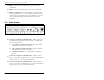
2. Unit Description 2.1. Front Panel As shown in Figure 2.1, the PLS-345 Front Panel includes the following components: Figure 2.1: Front Panel À Circuit 1: Status indicator lights and manual controls for Circuit 1. Includes the following: A) Line "A" Selector Button and Status LED: Press the "A" button to switch the common line for Circuit 1 to the "A" connector. The LED adjacent to the Selector Button will light when Line "A" is selected.
PLS-345 - Physical Layer Switch; User's Guide Ä RDY: Flashes when the PLS-345 is ready to receive commands. Å RXD: Flashes when the PLS-345 receives commands. Æ Master A/B Switch: Used to manually switch all three circuits. When the "A" or "B" button is pressed, all three circuits will be switched to the corresponding "A" or "B" line, and the appropriate status LED on each circuit will light. 2.2. Back Panel Figure 2.
Section 2: Unit Description à Network Port and Activity Indicator: An RJ45 Ethernet port, for connection to your TCP/IP network. To communicate via Network, please access the PLS-345 as described in Section 5.2. Note: The PLS-345 features a 10Base-T network interface. When connecting the PLS-345 to a 100Base-T interface, most router switches will autosense to determine if the device is 100Base-T or 10Base-T, and then configure the network interface accordingly.
PLS-345 - Physical Layer Switch; User's Guide 2-4
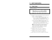
3. Quick Start / System Overview This section provides a brief overview of basic PLS capabilities, and describes a simple test that can be performed to verify that you are able to communicate with the unit. The Quick Start procedure is included primarily to provide a quick demonstration of PLS capabilities.
PLS-345 - Physical Layer Switch; User's Guide 3. Access the Command Mode: In order to invoke commands and display status screens, you must first access the PLS command mode via Network, modem, or Console Port (local PC.) For more information, on command mode access, please refer to Section 5.2. • • Notes: Network Access: The PLS includes a default IP Address and Subnet Mask.
Section 3: Quick Start / System Overview Physical Layer Switch v1.
PLS-345 - Physical Layer Switch; User's Guide Physical Layer Switch v1.
4. Installation 4.1. Power Supply Connection Connect the PLS-345 to an appropriate power supply. • • • CAUTIONS: This device should only be operated with the type of power source indicated on the instrument nameplate. If you are not sure of the type of power service available, please contact your local power company. Reliable earthing (grounding) of this unit must be maintained.
PLS-345 - Physical Layer Switch; User's Guide 4.3. Connecting Common and A/B Lines Connect your Cat5 cables to the appropriate A, B, and common line connectors on the PLS back panel. For a description of port interfaces, please refer to Appendix A. 4.4. Connecting the Network Cable The PLS Network Port is an RJ45, 10Base-T Ethernet Jack, for connection to a TCP/IP network. Connect your network interface to the PLS Network Port. The PLS features a default IP Address (192.168.168.168.
5. SetUp and Configuration 5.1. System Mode and User Mode In order to restrict access to sensitive command functions, the PLS-345 features two separate operating modes; System Mode and User Mode. The System Mode allows access to all configuration menus, A/B switching functions and status screens, and the User Mode allows access only to A/B switching functions and the status screens; when the User Mode is active, you are not allowed to access the configuration menus or reset the PLS Network Port.
PLS-345 - Physical Layer Switch; User's Guide 5.2. Communicating with the PLS-345 In order to configure the unit or invoke command functions, you must first connect to the PLS-345 and access the command mode. 1. Start your communications program (e.g. Hyperterminal.) Make certain that the PLS and your communications program are set for the same parameters (e.g. COM port, baud rate, etc.) 2.
Section 5: SetUp and Configuration Physical Layer Switch v1.
PLS-345 - Physical Layer Switch; User's Guide 5.3. PLS Command/Menu Conventions When invoking PLS commands or selecting items from configuration menus, note the following: · All PLS commands can be invoked at the PLS> command prompt, or from the General Parameters Menu, Circuit Parameters Menus, Monitor Parameters Menu, or Network Parameters Menu. · PLS commands are not case sensitive. · All PLS commands are invoked by pressing [Enter].
Section 5: SetUp and Configuration GENERAL PARAMETERS: 1. 2. 3. 4. 5. 6. 7. 8. 9. 10. System Password: User Password: Site ID: Modem Init. String: Modem Disc. String: Baud Rate: Command Echo: Inactivity Timeout: Command Confirmation: Automated Mode: A. Default Parameters (defined) (defined) PLS-345_TEST_IRVINE_CALIFORNIA ATE0M0Q1&C1&D2S0=1 (undefined) 38400,N,8,1 On 30 Min On Off Enter Selection or to Exit ... Figure 5.2: The General Parameters Menu 5.4.
PLS-345 - Physical Layer Switch; User's Guide 2. User Password: The User Password allows access to A/B switching commands and status screens, but does not allow access to the PLS configuration menus. To define the User Password, type 2, press [Enter] and follow the instructions in the submenu. (Up to 16 characters, casesensitive; Default = undefined.) Note: The PLS General Parameters Menu will not display the User Password. When the User Password has been defined, this field will read "(defined)". 3.
Section 5: SetUp and Configuration 7. Command Echo: Enables/disables command echo. When enabled, commands sent to the PLS will be echoed back to your PC, allowing keystrokes to be displayed. To enable or disable the command echo, type 7, press [Enter], and follow the instructions in the submenu. (Default = Off.) 8. Inactivity Timeout: Determines how long the PLS will wait for additional commands. Type 8, press [Enter], and follow the instructions in the submenu. (Default = 2 Min.) 9.
PLS-345 - Physical Layer Switch; User's Guide CIRCUIT #1 PARAMETERS: 1. 2. 3. 4. Common Name (From): "A" Name (To): "B" Name (To): Default Position: PORT_11111111111 PORT_AAAAAAAAAAA PORT_BBBBBBBBBBB A Enter Selection or to Exit ... Figure 5.3: The Circuit Parameters Menu 5.5. Circuit Parameters The Circuit Parameters menus are used to assign names and select default A/B positions for each of the switched A/B circuits. There is a separate Circuit Parameters menu for each A/B circuit.
Section 5: SetUp and Configuration 3. "B" Name (To): Assigns a name to the "B" line for this A/B circuit. When a name is assigned to the "B" line, and the circuit is in the "B" position, this name will appear in the "To" column on the PLS Circuit Status Screen. To assign a name to the "B" line, type 3, press [Enter], and follow the instructions in the submenu. (Up to 16 characters; Default = undefined.) 4.
PLS-345 - Physical Layer Switch; User's Guide NETWORK PARAMETERS: 1. 2. 3. 4. IP Address: Subnet Mask: Gateway Address: IP Security MAC Address: 65.106.93.114 255.255.255.0 65.106.93.97 52-54-40-22-48-7a Enter Selection or to Exit ... Figure 5.4: The Network Parameters Menu Note: Although new network port parameters can be specified via a network connection, newly selected parameters will not be applied until your telnet connection to the PLS has been terminated. 1.
Section 5: SetUp and Configuration IP SECURITY: 1. 2. 3. 4. 5. 6. 7. 8. 9. 10. Security Mask #1: Mask #1 Action: Security Mask #2: Mask #2 Action: Security Mask #3: Mask #3 Action: Security Mask #4: Mask #4 Action: Security Mask #5: Mask #5 Action: (undefined) Permit (undefined) Permit (undefined) Permit (undefined) Permit (undefined) Permit Enter Selection or to Exit ... Figure 5.5: The IP Security Menu 5.6.1.
PLS-345 - Physical Layer Switch; User's Guide Example 1: Deny access to all hosts except 192.1.1.5: Security Mask #1: 255.255.255.255 Security Mask #2: 192.1.1.5 Mask #1 Action: Deny Mask #2 Action: Permit Since 255 is a wild card, Mask #1 blocks all IP Addresses. Mask #2 then specifically grants access to 192.1.1.5 only. Example 2: Allow access only by addresses that begin with 192. Security Mask #1: 255.255.255.255 Security Mask #2: 192.255.255.
Section 5: SetUp and Configuration 5.7. The Monitor Mode The Monitor Mode allows the PLS-345 perform automatic A/B switching in response to signal changes at the monitor port on the instrument back panel. The Monitor Mode can be set to monitor a Contact or an RS-232 Line. 5.7.1. Hardware Configuration In order to employ the Monitor Mode, you must first connect the monitored line to the PLS unit, and configure the Monitor Selector Switch as follows: 1.
PLS-345 - Physical Layer Switch; User's Guide MONITOR PARAMETERS: 1. 2. 3. 4. 5. 6. Monitor Mode: Switch If Level: Switch to Position: Delay Period: Return: Circuits to Switch: On 0 - Low B .5 Secs On 2, 3 Enter Selection or to Exit ... Figure 5.6: The Monitor Mode Parameters Menu 1. Monitor Mode: Enables/disables the Monitor Mode feature. Do not enable the Monitor Mode until you have finished selecting the other Monitor Mode parameters. (Default = Off.) 2.
Section 5: SetUp and Configuration 5. Return: When enabled, the Monitor Mode will return the switched A/B circuit(s) to the original A/B position if the monitored signal also returns to its normal state. (Default = Off.) For example, assume the Monitor Mode is configured as follows: · Switch if Level: 1 - High · Switch to Position: B · Return: On If the circuit starts in position "A", and the monitored line goes high, then the circuit will be switched to the "B" position.
PLS-345 - Physical Layer Switch; User's Guide 5.8. Save Configuration Parameters After the unit has been completely configured, it is recommended to save parameters to an ASCII file as described in Section 8. This allows quick recovery in the event that the unit is reset to default parameters, or if the configuration is accidentally deleted or altered.
6. The Status Screens The PLS Status Screens are used to display current conditions of the three switched A/B circuits and the network interface. There are two status screens; the Circuit Status Screen (/S), and the Network Status Screen (/SN). 6.1. The Circuit Status Screen The Circuit Status Screen lists the current A/B settings for the PLS-345's three switched circuits, and also summarizes userselected parameters, such as Command Echo, Inactivity Timeout, and Command Confirmation.
PLS-345 - Physical Layer Switch; User's Guide 6-2 3. From: The user-defined name for the Common Line (C) for each of the three A/B circuits. Note that if the Common Line name has not been defined, this field will remain empty. 4. To: The user defined name for the currently selected "A" or "B" line for each of the three A/B circuits. Note that if the A/B line names have not been defined, this field will remain empty. 5.
Section 6: The Status Screens Physical Layer Switch v1.00 Site ID: PLS-345_TEST_IRVINE_CALIFORNIA NETWORK STATUS: 52-54-40-22-48-7a TCB 1 SRC PORT 16128 PORT Telnet TCB 1 STATE Established SOURCE IP ADDR 65.106.93.98 STATE Connected PLS> Figure 6.2: The Network Status Screen 6.2. The Network Status Screen The Network Status Screen lists the TCP port number, source port, source IP address and other Network related parameters.
PLS-345 - Physical Layer Switch; User's Guide 6-4
7. Operation The PLS-345 offers three different methods for switching A/B paths: 1. Manual A/B Switching: The manual A/B Switches on the PLS front panel are used to initiate switching of one or more A/B Circuits. 2. Code Activated A/B Switching: ASCII commands are sent to the PLS to initiate switching of one or more A/B Circuits. 3.
PLS-345 - Physical Layer Switch; User's Guide 7.2. Code Activated A/B Switching The PLS offers three different commands for controlling A/B switching: · The /A command, which is used to switch one or more circuits to the "A" line. · The /B command, which is used to switch one or more circuits to the "B" line. · The /D command, which is used to switch all three circuits to their user-defined default A/B positions. All three of these commands are available in both System Mode and User Mode. 7.2.1.
Section 7: Operation The Command Confirmation Prompt: Normally, when the /A or /B commands are invoked, the PLS will prompt you for confirmation before actually implementing the command. If you wish to suppress this confirmation prompt, and execute commands without confirmation, you can employ one of the following methods: · Include the ",y" option in the command line (e.g. /A 1,y.) · Disable Command Confirmation as described in Section 5.4. · Enable the Automated Mode as described in Section 5.4. 7.2.2.
PLS-345 - Physical Layer Switch; User's Guide 7.3. The Monitor Mode The Monitor Mode allows the PLS-345 perform automatic A/B switching in response to signal level changes at the monitor port on the instrument back panel. The Monitor Mode can be set to monitor a Contact or an RS-232 Line. For more information on the Monitor Mode, please refer to Section 5.7.
8. Saving and Restoring Configuration Parameters After the PLS has been properly configured, parameters can be downloaded and saved as an ASCII text file. Later, if the configuration is accidentally altered, the file with the saved parameters can be uploaded to automatically reconfigure the unit without the need to manually assign each parameter. Saved parameters can also be uploaded to other PLS units. This allows rapid set-up when several units will be configured with the same parameters.
PLS-345 - Physical Layer Switch; User's Guide 4. The PLS will send a series of ASCII command lines which specify the currently selected PLS parameters. The last line of the file should end with a “/G-00” command. When the download is complete, press [Enter] to return to the "PLS>" command prompt. 8.2. Restoring Saved Parameters This section describes the procedure for using your terminal emulation program to send stored parameters to the PLS. 1.
9. Application Examples 9.1. Monitoring Signal Drop and/or Power Loss In this application, the PLS-345 will monitor the DTR signal from a data device. If the signal drops or the data device loses power for more than one minute, the unit will automatically switch circuits 2 and 3 to the "B" line. Figure 9.1: Monitoring Signal Drop 1. Connect Line from Data Device: Connect a line from the Data Device to the Monitor Input Connector as shown in Figure 9.1. 2.
PLS-345 - Physical Layer Switch; User's Guide Figure 9.2: AUX Port Connection 3. Configure Monitor Mode: Access the PLS command mode as described in Section 5.2. At the PLS> command prompt, type /M [Enter] to display the Monitor Mode Parameters Menu. Note that the Monitor Mode Parameters Menu is not available in User Mode. Set Monitor Mode Parameters as follows: a) Item 1 - Monitor Mode: On. Note: Do not enable the Monitor Mode until you have finished defining the other Monitor Mode parameters.
Section 9: Application Examples Figure 9.3: Monitoring a Switch or Relay 9.2. Monitoring a Contact In this application, the PLS will monitor a switch or contact. When the contact closes (signal goes low) for more than one minute, the PLS will automatically switch module 1 to the "B" position. Later, if the contact returns to the open position, the PLS will return circuit 1 to the "A" position. Note: This example could also be used to monitor a contact or switch that is normally closed.
PLS-345 - Physical Layer Switch; User's Guide Figure 9.4: AUX Port Connection 3. Configure Monitor Mode: Access the PLS command mode as described in Section 5.2. At the PLS> command prompt, type /M [Enter] to display the Monitor Mode Parameters Menu. Note that the Monitor Mode Parameters Menu is not available in User Mode. Set Monitor Mode Parameters as follows: a) Item 1 - Monitor Mode: On. Note: Do not enable the Monitor Mode until you have finished defining the other Monitor Mode parameters.
10. Command Summary All PLS-345 commands conform to the following standards: · All commands normally begin with the "/" (foreword slash) character. If you wish to temporarily suppress command echo, use the "\" (backward slash) character instead of a forward slash. · All command lines are invoked by pressing the [Enter] key. · Both the System Level Password and User Level Password are case sensitive. 10.1.
PLS-345 - Physical Layer Switch; User's Guide /SN Display Network Status Displays a status screen (Figure 6.2), which lists current network parameters, such as the TCB port, Telnet port, and network status. Command Format: /SN [Enter] Response: Displays Network Status Screen, followed by the PLS> command prompt. Command Availability: System and User. 10.2. Configuration Commands These commands are used to access the configuration menus, which are used to select operating parameters for the PLS-345.
Section 10: Command Summary /N View/Set Network Parameters Displays the Network Parameters Menu (Figure 5.4), which is used to define the IP Address, Subnet Mask, Gateway Address and access the IP Security Menu. For more information on the Network Parameters Menu, please refer to Section 5.6. Command Format: /N [Enter] Response: Displays Network Parameters Menu. Command Availability: System Only. /M View/Set Monitor Mode Parameters Displays the Monitor Mode Parameters Menu (Figure 5.
PLS-345 - Physical Layer Switch; User's Guide 10.3. Control Commands These commands are used to switch A/B lines at each circuit, set circuits to default status, and reset the network interface. /A Switch Circuit "n" to Line "A" Switches the target circuit(s) to Line "A". Note that this command can be used to switch one circuit, a combination of circuits or all circuits to the "A" state. For more information, please refer to Section 7.2.1.
Section 10: Command Summary /D Set Circuits to Default Switches all PLS-345 circuits to their default A/B state. Note that the default A/B state is set using the Circuit Parameters Menu, as described in Section 7.2.2. Command Format: /D [Enter] Command Arguments: ,y Suppress Confirmation (Sure) Prompt. For example, "/D,y" switches all circuits to their default states without displaying the confirmation prompt.
PLS-345 - Physical Layer Switch; User's Guide /X Exit/Disconnect Exits from command mode. When you have contacted the PLS via network, the unit will exit command mode and the network connection will be terminated. When you have contacted the PLS via modem, the unit will exit command mode and the modem will hang up. When you have contacted the PLS via a local PC connected to the PLS Console Port, the unit will exit command mode.
A. Interface Descriptions A.1 Console Port Interface Figure A.1: Console Port Interface A.2 Modem Port Interface Figure A.
PLS-345 - Physical Layer Switch; User's Guide A.3 Common Ports and A/B Ports Figure A.
Appendices B. Specifications Interface: RJ-45, three jacks, Cat5 compliant, capable of switching 10/100Base-T with minimum dB loss, 8 pins switched, Common Jack to "A" or "B" Jack. Contacts: High reliability, mechanical relays, break-beforemake contacts with 1 amp @ 30 VDC rating, 100 million cycle life. Switching: Manual: Individual or ALL from front panel controls. Code: By circuit number or name. Network Port: 10BaseT Ethernet, RJ45. Console Port: RS-232, DB-9M, DTE pinout.
PLS-345 - Physical Layer Switch; User's Guide C. Customer Service Customer Service hours are from 8:00 AM to 5:00 PM, PST, Monday through Friday. When calling, please be prepared to give the name and make of the unit, its serial number and a description of its symptoms. If the unit should need to be returned for factory repair it must be accompanied by a Return Authorization number from Customer Service.
Index # 100BaseT Networks 2-3, 4-2 A A Name (To) 5-8 A/B Lines 4-2 A/B Settings 6-1 to 6-2 A/B Switching 7-1 to 7-4, 10-4 Code Activated 7-2 Manual 7-1 Monitor Mode 9-1 A/C/B Circuits Apx-2 A/C/B Indicators 2-1 Application Examples 9-1 to 9-4 Automated Mode 5-7 Automatic A/B Switching 5-13 to 5-15 B Name (To) Back Panel Baud Rate Circuit Circuit Circuit Circuit Circuit B C Default Indicators Name Number Parameters Menus 5-9 2-2 to 2-3 5-6 5-9 2-1 5-8 6-1 5-8 to 5-9, 10-2 Circuit Status Screen 6-1 t
PLS-345 - Physical Layer Switch; User's Guide M MAC Address 5-10, 6-3 Manual A/B Switching 7-1 Manual Switch 2-2 Master A/B Switch 2-2 Menu Conventions 5-4 Modem Access 5-2 Modem Port 2-3, 4-2, 5-2, Apx-1 Disconnect String 5-6 Initialization String 5-6 Monitor Input 5-13 Monitor Input Connector 2-3 Monitor Mode 2-3, 5-13 to 5-15, 6-2, 7-4, 9-1 to 9-4 Contact 9-3 Examples 9-2 Hardware Configuration 5-13 Parameters Menu 5-13 Monitor Selector Switch 2-3, 5-13, 9-1 Monitoring Signal Drop 9-1 to 9-2 N Networ
5 Sterling · Irvine · California 92618 · Toll Free: 1-800-854-7226 (949) 586-9950 · http://www.wti.