
Video Gaming Accessories User Manual


2-2
Unit Description
O
I
PHONE
LINE
10/100BaseT
LINK
ACTIVITY
SYSTEM SETUP PORTS
(DTE)
1 2 3 4 5 6 7 8
1
2
3
4
5
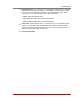
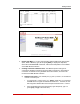
Figure 2.2: Instrument Back Panel (Model RSM-8)
O
I
PHONE
LINE
10/100BaseT
LINK
ACTIVITY
2
1
3
4
5
6
7
8
9
10
11
12
13
14
15
16
SYSTEM
SETUP
PORTS
(DTE)
1
2
3
3
4
5
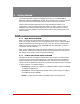
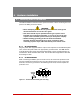
Figure 2.3: Instrument Back Panel (Model RSM-16)
PHONE
LINE
10/100BaseT
LINK
ACTIVITY
2
1
3
4
5
6
7
8
9
10
11
12
13
14
15
16
18
17
19
20
21
22
23
24
25
26
27
28
29
30
31
32
SYSTEM
SETUP
PORTS
(DTE)
1
2
3
3
4
5
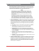
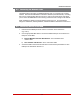
Figure 2.4: Instrument Back Panel (Model RSM-32)
2.2. Back Panel
As shown in Figures 2.2, 2.3 and 2.4, the RSM Back Panel includes the following
components:
Phone Line Port: For connection to your external phone line.
Network Port: An RJ45 Ethernet port for connection to your 10/100Base-T, TCP/IP
network. Note that the RSM features a default IP address (192.168.168.168). This
allows you to connect to the unit without first assigning an IP address. Note that the
Network Port also includes two, small LED indicators for Link and Data Activity. For
more information on Network Port configuration, please refer to Section 5.8.