WTI Part No. 12114 Rev. D CAS-161A Code Activated Switch User’s Guide 5 Sterling · Irvine · California 92618 (949) 586-9950 · Toll Free: 1-800-854-7226 Fax: (949) 583-9514 · http://www.wti.
Table of Contents 1. Introduction . . . . . . . . . . . . . . . . . . . . . . . . . . . . . . . . . . . . . . . . . . . . . 1-1 2. Unit Description . . . . . . . . . . . . . . . . . . . . . . . . . . . . . . . . . . . . . . . . . . 2-1 2.1. Front Panel Indicators . . . . . . . . . . . . . . . . . . . . . . . . . . . . . . . . . . . . 2-1 2.2. Back Panel Components . . . . . . . . . . . . . . . . . . . . . . . . . . . . . . . . . . . 2-2 3. Installation . . . . . . . . . . . . . . . . . . . . . . . . .
1. Introduction The CAS-161A Code Activated Switch enables a single RS232 Control port to switch between 16 to 64 ports via an ASCII code sequence. The code sequence is a user-selectable Prefix code and a Port Select code. The Prefix code is set via the Setup switch on the bottom of the unit. For added security, the Setup switch can be set to require one, two, four or eight of the same Prefix codes.
2. Unit Description Figure 2.1: Instrument Front Panel 2.1. Front Panel Indicators À PWR: (Power) Indicates power to the unit is ON. Á TXD: (Transmit Data) Indicates data is being transmitted out pin 2 of the Control port (MODEM Port). Indicates data is being received at pin 2 of the selected port. Â RXD: (Receive Data) Indicates data is being received at pin 3 of the Control port. Ã RTS: (Request to Send) Indicates high RS232 signal at pin 4 (output) of the Control port.
CAS-161A Code Activated Switch, User's Guide Unit Description Figure 2.2: Instrument Back Panel 2.2. Back Panel Components À Input Ports 1 - 16: Ports labeled 1 - 16 are 25-pin, female, RS232 connectors. Optional RS422 connectors can be factory installed to increase data transmission distance. For a description of the port interface, please refer to Appendix A. Á MODEM Port (Control Port): A 25-pin, female, RS232 connector. For a description of the port interface, please refer to Appendix A.
3. Installation 3.1. Configure SetUp Switches There are two banks of DIP switches located on the bottom of the CAS-161A unit. These switches are used to configure the Prefix Code (command character), enable the Broadcast Mode, and select the baud rate. Switch functions are summarized on the bottom of the unit and in the sections that follow: Note: Switch positions “1” and “0” are indicated on the bottom of the unit. 3.1.1.
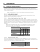
CAS-161A Code Activated Switch, User's Guide Installation 3.1.1.3. Baud Rate Select (Sw6 - Sw8) Selects the operating baud rate; from 150 to 19.2K baud.
CAS-161A Code Activated Switch, User's Guide Installation 3.1.2. SetUp Switch Bank 2 The bank of DIP switches located closest to the front panel are used to select the Prefix Code character and set the parity. 3.1.2.1. Prefix Code (Sw1 - Sw7) As mentioned previously, the Prefix Code informs the unit that the next character will be a command. The Prefix code can be any ASCII character. However, since it is passed on to the connected device, it is recommended to use a non-printable character.
CAS-161A Code Activated Switch, User's Guide Installation 3.1.2.2. Parity (Sw8) Parity can be set to Even, Mark, Odd, None, or Space. Switch 8 (Bank 2) Parity 1 (On) X Even, Mark Odd, None, Space 0 (Off) X 3.2. Connect Power Cable 1. Make certain the power switch is in the OFF position. 2. Attach one end of the power cable to the AC power connector on the CAS-161A. Attach the other end to a grounded wall outlet. 3.3. Connect Data Cables Note: Check to make certain all data cables are compatible.
4. Port Selection 4.1. Selecting a Port 1. After completing the installation procedure, flip the power switch on the back of the unit to ON. Note: Upon each power-up the unit will reset and all ports will be closed. 2. Refer to the Port Select Code Chart below and find the letter representing the port you wish to connect to.
CAS-161A Code Activated Switch, User's Guide Port Selection Examples: Assume the Prefix Code is ^V and the Prefix Code Repetition Value is 4. To connect to Port 14, use the following command: ^V^V^V^VM Assume the Prefix Code is ^Y and the Prefix Code Repetition Value is 1. To connect to Port 44, use the following command: ^Yk 4.2. Closing/Opening All Ports 1. To close all ports at once, enter the Prefix code, followed by a space. 2.
A. Interface Description A.1. RS232 Ports (Standard) Figure A.1: RS232 Interface A.2. RS422 Ports (Optional) Figure A.2: RS422 Interface Note: Handshake signals are not passed. Pins 1 - 13 are open.
CAS-161A Code Activated Switch Appendices B. Printable Prefix Codes Since the Prefix code is transmitted through the opened port, it is best to select a non-printable Prefix Code. The procedure for selecting the Prefix Code is described in Section 3. If your application requires a printable code, refer to the ASCII code chart below. Remember: · Switch positions 1 - 7 correspond to ASC bits B1 - B7 on the chart. · Switch positions should be ON for a 0 and OFF for a 1.
CAS-161A Code Activated Switch C. Appendices Installing Add-On Modules The CAS-161A is field expandable to 32, 48, or 64 ports by attaching up to three additional Add-On Modules to the master unit. Each Add-On Module Kit includes the following: · 1 ea. · 2 ea. · 1 ea. · 1 ea. · 18 ea. Add-On Module w/ six-wire power cable Connecting Plates Left Rack-Mount Bracket (Style-2) Right Rack-Mount Bracket (Style-2) 6-32 x 3/8” Screws To install Add-On Modules, refer to Figure C.
CAS-161A Code Activated Switch Appendices 1. Remove the instrument top cover. If your unit has a stand-alone top cover, remove the cover; the stand-alone cover is no longer required. If your unit has a Rack-Mount Kit, remove the Rack-Mount Cover, Left and Right Rack-Mount Brackets (Style 1), and screws. Save these parts, they will be used later. 2. Locate and unroll the ribbon cable (A) from inside the Master Unit. Hold the Add-On Module (B) over the Master Unit (C).
CAS-161A Code Activated Switch Appendices D. Specifications Coding: ASCII, Asynchronous Baud Rate: 300 to 19.2K baud, Switch Selectable Interface: RS232, 25-pin connectors Lines Switched: 2,3,4 and 5. Pins 6 and 8 of all Input ports follow Pin 6 of the Control port. Power: 90 VAC to 130 VAC (jumper-selectable), 180 VAC to 260 VAC, 47 to 450 Hz. Ambient Temp: 25° Operating Temp: 0° C to 38° Ventilation: 2" all sides Size: 17.25" x 3.50" x 9.
CAS-161A Code Activated Switch E. Appendices Customer Service Customer Service hours are from 8:00 AM to 5:00 PM, PST, Monday through Friday. When calling, please be prepared to give the name and make of the unit, its serial number and a description of its symptoms. If the unit should need to be returned for factory repair it must be accompanied by a Return Authorization number from Customer Service.
CAS-161A Code Activated Switch F. Appendices FCC Statement WARNING: This equipment generates, uses and can radiate radio frequency energy and if not installed and used in accordance with the instruction manual, may cause interference to radio and television reception.
CAS-161A Code Activated Switch Appendices Trademark and Copyright Information WTI, WTI logo and Western Telematic are trademarks of Western Telematic Inc. All other product names mentioned in this publication are trademarks or registered trademarks of their respective companies. Information and descriptions contained herein are the property of Western Telematic Inc.