WTI Part No. 13662 Rev. D RSM Series Remote Site Managers Models Covered: RSM-8 RSM-16 RSM-16DC RSM-32 RSM-32DC For Firmware Version 2.
Warnings and Cautions: Installation Instructions Secure Racking If Secure Racked units are installed in a closed or multi-unit rack assembly, they may require further evaluation by Certification Agencies. The following items must be considered. 1. The ambient within the rack may be greater than room ambient. Installation should be such that the amount of air flow required for safe operation is not compromised. The maximum temperature for the equipment in this environment is 45°C.
Warnings and Cautions Disconnect Power If any of the following events are noted, immediately disconnect the unit from the outlet and contact qualified service personnel: 1. If the power cord becomes frayed or damaged. 2. If liquid has been spilled into the device or if the device has been exposed to rain or water.
Agency Approvals FCC Part 15 Regulation This equipment has been tested and found to comply with the limits for a Class A digital device, pursuant to part 15 of the FCC Rules. These limits are designed to provide reasonable protection against harmful interference when the equipment is operated in a commercial environment.
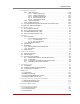
Table of Contents 1. Introduction . . . . . . . . . . . . . . . . . . . . . . . . . . . . . . . . . . . . . . . . . . . . . . . . . . . . . . . . . . . . . 1-1 2. Unit Description. . . . . . . . . . . . . . . . . . . . . . . . . . . . . . . . . . . . . . . . . . . . . . . . . . . . . . . . . . 2-1 2.1. Front Panel . . . . . . . . . . . . . . . . . . . . . . . . . . . . . . . . . . . . . . . . . . . . . . . . . . . . . . . . . . . . 2-1 2.2. Back Panel . . . . . . . . . . . . . . . . . . . . . . . . . . . .
Table of Contents 5. Configuration (continued) 5.8.7. LDAP Parameters . . . . . . . . . . . . . . . . . . . . . . . . . . . . . . . . . . . . . . . . . . . . . . . 5.8.7.1. Adding LDAP Groups . . . . . . . . . . . . . . . . . . . . . . . . . . . . . . . . . . . . 5.8.7.2 Viewing LDAP Groups . . . . . . . . . . . . . . . . . . . . . . . . . . . . . . . . . . . . 5.8.7.3. Modifying LDAP Groups . . . . . . . . . . . . . . . . . . . . . . . . . . . . . . . . . . 5.8.7.4. Deleting LDAP Groups . . . . . . . . . .
Table of Contents Appendices: A. RS232 Port Interface . . . . . . . . . . . . . . . . . . . . . . . . . . . . . . . . . . . . . . . . . . . . . . . . . . . . Apx-1 B. Specifications . . . . . . . . . . . . . . . . . . . . . . . . . . . . . . . . . . . . . . . . . . . . . . . . . . . . . . . . . Apx-2 C. Customer Service . . . . . . . . . . . . . . . . . . . . . . . . . . . . . . . . . . . . . . . . . . . . . . . . . . . . . . Apx-3 Index. . . . . . . . . . . . . . . . . . . . . . . . . . . . . . . . . . .
Table of Contents List of Figures 2.1. 2.2. 2.3. 2.4. 3.1. 3.2. 4.1. 5.1. 5.2. 5.3. 5.4. 5.5. 5.6. 5.7. 5.8. 5.9. 5.10. 5.11. 5.12. 5.13. 5.14. 5.15. 5.16. 5.17. 5.18. 5.19. 5.20. 5.21. 5.22. 5.23. 5.24. 5.25. 5.26. 5.27. 5.28. 5.29. 5.30. 5.31. 5.32. 5.33. 5.34. 5.35. 5.36. 5.37. 5.38. 6.1. 6.2. 6.3. 6.4. 6.5. 9.1. A.1. Instrument Front Panel (Model RSM-8 Shown) . . . . . . . . . . . . . . . . . . . . . . . . . . . . . . . . . 2-1 Instrument Back Panel (Model RSM-8) . . . . . . . . . . . . . . . . . . .
1. Introduction The RSM-8, RSM-16, RSM-16DC, RSM-32 and RSM-32DC Remote Site Managers provide in-band and out-of-band access to RS-232 console ports and maintenance ports on UNIX servers, routers and any other network element that includes a serial console port. System administrators can access the RSM via TCP/IP network, using SSH or Telnet, or out-of-band via modem or local terminal.
Introduction Configuration Backup Once you have configured the RSM to fit your application, parameters and options can be saved to an ASCII text file on your PC. This allows you to quickly restore userselected parameters if unit configuration is accidentally altered or deleted. Saved parameters can also be uploaded to other RSM units. This allows rapid set-up when several units will be configured with identical or similar parameters.
2. Unit Description 2.1. Front Panel RSM-8 www.wti.com ON CLEAR 1 2 3 SET RDY 4 CONNECTIONS 1 2 3 4 5 6 7 8 Remote Site Manager 5 Figure 2.1: Instrument Front Panel (Model RSM-8 Shown) CLEAR: Restarts the RSM without changing user-selected parameter settings. Note: When Clear is pressed, all ports will be disconnected. ON: Lights when AC Power is applied. SET: Used to Initialize the RSM to default parameters.
Unit Description 2.2. Back Panel As shown in Figures 2.2, 2.3 and 2.4, the RSM Back Panel includes the following components: Phone Line Port: For connection to your external phone line. Network Port: An RJ45 Ethernet port for connection to your 10/100Base-T, TCP/IP network. Note that the RSM features a default IP address (192.168.168.168). This allows you to connect to the unit without first assigning an IP address.
Unit Description RS232 Serial Ports: For connection to console ports on target devices. Standard DB9 connectors configured as DTE ports. The RS232 ports are similar to a serial port on a PC. When connecting a modem, use a standard serial cable. When connecting a PC or other DTE device use a null modem cable. • RSM-8 units include 8 Serial Ports. • RSM-16 and RSM-16DC units include 16 Serial Ports. • RSM-32 and RSM-32DC units include 32 Serial Ports.
3. Getting Started This section describes a simplified installation procedure for our RSM-8, RSM-16, RSM-16DC, RSM-32 and RSM-32DC models, which will allow you to communicate with the unit in order to demonstrate basic features and check for proper operation. Note that this Quick Start Guide does not provide a detailed description of unit configuration, or discuss advanced operating features in detail.
Getting Started 3.2. Communicating with the RSM When properly installed and configured, the RSM will allow command mode access via Telnet, Web Browser, SSH client, modem, or local PC. However, in order to ensure security, both Telnet and Web Browser access are disabled in the default state. To enable Telnet and/or Web Browser access, please refer to Section 5.8. Notes: • Default RSM serial port parameters are set as follows: 9600 bps, RTS/ CTS Handshaking, 8 Data Bits, One Stop Bit, No Parity.
Getting Started PORT STATUS: Site ID: (undefined) 02/07/2007 00:23:39 GMT (GMT+0000) PORT | NAME | USERNAME | STATUS | MODE | BUFFER COUNT -----+------------------+------------------+--------+--------+-------------01 | (undefined) | | Free | Any | 0 02 | (undefined) | | Free | Any | 0 03 | (undefined) | | Free | Pass | 0 04 | (undefined) | | Free | Pass | 0 05 | (undefined) | | Free | Pass | 0 06 | (undefined) | | Free | Pass | 0 07 | (undefined) | | Free | Pass | 0 08 | (undefined) | | Free | Pass | 0 09 | MODEM
Getting Started b) 5. Third Party Connection: Your resident port (e.g. Port 1) issues a /C command to create a connection between two other ports. i. To connect Port 2 to Port 3, type /C 2 3 [Enter]. ii. While Ports 2 and 3 are connected, Port 1 will still recognize RSM commands. Type /S [Enter] to display the Port Status Screen. The "STATUS" column should now list Ports 2 and 3 as connected, and Port 1 as "Free". iii.
4. Hardware Installation 4.1. Connecting Power to the RSM Unit The RSM is available in both AC and DC powered versions. When connecting AC or DC power to the RSM, proceed as follows: CAUTIONS: • Before attempting to install this unit, please review the warnings and cautions listed at the front of the user's guide. • This device should only be operated with the type of power source indicated on the instrument nameplate.
Hardware Installation 4.2. Connecting the Network Cable The Network Port is an RJ45, 10/100BaseT Ethernet Jack, for connection to a TCP/IP network. Note that the RSM features a default IP Address (192.168.168.168.) Providing that you are communicating with the unit from a node on the same subnet, this allows you to contact the RSM without first accessing command mode to assign an IP address.
5. Configuration 5.1. Communicating with the RSM Unit In order to configure the RSM, you must first connect to the unit, and access command mode. Note that, the RSM offers two separate configuration interfaces; the Web Browser Interface and the Text Interface. In addition, the RSM also offers three different methods for accessing command mode; via network, via modem, or via local console.
Configuration To access command mode via the Text Interface, proceed as follows: Note: Command mode cannot be accessed via a Buffer Mode Port, Passive Mode Port, or any port that is presently connected to another RSM port. 1. Contact the RSM Unit: a) Via Local PC: Start your communications program and press [Enter]. Wait for the connect message, then proceed to Step 2. b) Via Network: The RSM includes a default IP address (192.168.168.168) and a default subnet mask (255.255.255.0.
Configuration 3. If a valid username and password are entered, the RSM will display the Port Status Screen, shown in Figure 5.1. Note: If the Telnet connection is refused, it is most likely due to one of the following reasons: • The IP Security feature has denied the connection. • You are attempting to use an account that permits Supervisor commands to connect to a port that does not permit Supervisor Commands. 5.1.2.
Configuration 5.2. System SetUp Ports Serial Ports 1 and 2 are reserved as SetUp Ports, and will always permit password protected access to Supervisor commands. Therefore, Ports 1 and 2 cannot be configured as Buffer Mode Port or Passive Mode Ports, because these port modes do not permit access to command mode. In addition, the Supervisor Mode cannot be disabled at Ports 1 and 2. 5.3.
Configuration 5.4. Defining System Parameters The System Parameters menus are used to define the Site ID Message, set the system clock and calendar, and configure the Invalid Access Lockout feature and Callback feature. SYSTEM PARAMETERS: 1. 2. 3. 4. 5. 6. 7. User Directory Site-ID: Real Time Clock: Invalid Access Lockout: Audit Log: Callback Security: “/PW” Command: 01/09/2007 00:26:06 On On - Without Syslog On - Callback (Without Password Prompt) Off Enter: # to change, exit ... Figure 5.
Configuration In the Text Interface, the System Parameters menu is also used to create and manage user accounts and passwords. Note however, that when you are communicating with the unit via the Web Browser Interface, accounts and passwords are managed and created via a separate menu that is accessed by clicking on the "Users" link on the left hand side of the menu. • Text Interface: Type /F and press [Enter]. The System Parameters Menu will appear as shown in Figure 5.3.
Configuration 5.4.1. The Real Time Clock and Calendar The Real Time Clock menu is used to set the RSM's internal clock and calendar. To access the Real Time Clock Menu, proceed as follows: • Text Interface: Type /F and press [Enter]. The System Parameters menu will appear as shown in Figure 5.3. At the System Parameters menu, type 3 and press [Enter] to display the Real Time Clock menu.
Configuration • Secondary NTP Address: Defines the IP address or domain name (up to 64 characters long) for the secondary, fallback NTP Server. (Default = undefined.) • NTP Timeout: The amount of time in seconds, that will elapse between each attempt to contact the NTP server. When the initial attempt is unsuccessful, the RSM will retry the connection four times. If neither the primary nor secondary NTP server responds, the RSM will wait 24 hours before attempting to contact the NTP server again.
Configuration The Invalid Access menus allow you to select the following: • Lockout Enable: Enables/Disables the Invalid Access Lockout feature. (Default = On.) • Lockout Attempts: The number of invalid attempts required to activate the Invalid Access Lockout feature. (Default = 9.) • Lockout Duration: The length of time ports will remain locked when an Invalid Access Lockout occurs. If the duration is set at "Infinite", then ports will remained locked until the /UL command is issued.
Configuration 5.4.4. Callback Security The Callback function provides an additional layer of security when callers attempt to access command mode via modem. When this function is properly configured, modem users will not be granted immediate access to command mode upon entering a valid password; instead, the unit will disconnect, and dial a user-defined number before allowing access via that number. If desired, users may also be required to re-enter the password after the RSM dials back.
Configuration ◆ On - Callback ONLY (Without Password Prompt): Callbacks will be performed for user accounts that include a Callback Number, and the username/password prompt will not be displayed when the user’s modem answers. Accounts that do not include a Callback Number will not be able to access command mode via an RSM modem port.
Configuration 5.5. User Accounts Prior to accessing command mode or establishing a Telnet Direct Connection, you will be prompted to enter a username (login) and password. The username and password entered at login determine which port(s) you will be allowed to connect and what type of commands you will be allowed to execute. Each username / password combination is defined within a "user account.
Configuration 5.6. Managing User Accounts The User Directory function is employed to create new accounts, display parameters for existing accounts, modify accounts and delete accounts. Up to 128 different user accounts can be created. The "User Directory" function is only available when you have logged into command mode using an account and port that permit Supervisor commands. • Text Interface: Type /F and press [Enter] to access the System Parameters Menu.
Configuration ADD USERNAME TO DIRECTORY: 1. 2. 3. 4. Username: Password: Supervisor Access: Port Access: (undefined) Off PORT# PORT NAME ACCESS ------------------------------1 (undefined) Off 2 (undefined) Off 3 (undefined) Off 4 (undefined) Off 5 (undefined) Off PORT# PORT NAME ACCESS ------------------------------6 (undefined) Off 7 (undefined) Off 8 (undefined) Off 9 MODEM Off 5. Callback Phone #: Enter: # to select, to return to previous menu ... Figure 5.
Configuration To create new user accounts, proceed as follows: • Text Interface: From the User Directory menu, type 2 and press [Enter]. The Add Username menu (Figure 5.5) will be displayed. • Web Browser Interface: From the Edit User menu, click the "Add User" link. The RSM will display the Add User menu (Figure 5.6.) The Add Username Menu can be used to define the following parameters for each new account: • Username: Up to 32 characters long, and cannot include non-printable characters.
Configuration 5.6.3. Modifying User Accounts The "Edit User Directory" function allows you to edit existing user accounts in order to modify passwords and usernames, or change port access or Supervisor Command capability. Note that the Edit/Modify User function is only available to users who have accessed command mode using a password that permits Supervisor Level commands. To modify a user account, proceed as follows: • Text Interface: From the User Directory menu, type 3 and press [Enter].
Configuration 5.7. RS232 Port Configuration When responding to prompts, invoking commands, and selecting items from port configuration menus, note the following: • Configuration menus are only available to accounts and ports that permit Supervisor commands. • If you are configuring the RSM via modem, modem parameters will not be changed until after you exit command mode and disconnect from the RSM. 5.7.1.
Configuration PORT PARAMETERS #03: COMMUNICATION SETTING 1. Baud Rate: 2. Bits/Parity: 3. Stop Bits: 4. Handshake: 9600 8-None 1 RTS/CTS GENERAL PARAMETERS 11. Supervisor Mode: 12. Logoff Char: 13. Sequence Disc: 14. Inact Timeout: 15. Command Echo: 16. Accept Break: Permit ^X One Char 5 Min On On PORT MODE PARAMETERS 21. Port Name: 22. Port Mode: 23. DTR Output: 24. Buffer Params: 25. Modem Params: Passive Pulse ----- NETWORK SERVICES 31. Direct Connect: Telnet Port: SSH Port: Raw Port: 32.
Configuration 5.7.2. RS232 Port Configuration Menus The Port Configuration Menus are used to select communications parameters and enable/disable options for each RS232 port. • Text Interface: Type /P n and then press [Enter] (Where n is the number or name of the desired RS232 Serial Port.) The Port Parameters menu will be displayed as shown in Figure 5.7. • Web Browser Interface: Click the "Serial Port" link on the left hand side of the screen to display the Port Selector Menu.
Configuration General Parameters: • Supervisor Mode: Permits/denies port access to supervisor commands. When enabled (Permit), the port will be allowed to invoke supervisor commands, providing the unit is accessed using an account that permits them. If disabled (Deny), the port may not invoke Supervisor commands. (Default = Permit). Note: If the Supervisor Mode is set to "Deny", then user accounts that permit Supervisor commands will not be allowed to access command mode via this port.
Configuration Port Mode Parameters: • Port Mode: The operation mode for this port. Ports 1 and 2 cannot be configured as Passive or Buffer Mode ports, and the internal modem port is always configured for Modem Mode. (Port 1 and 2, Default = Any-to-Any Mode; Serial Ports 3 and above, Default = Passive Mode; Internal Modem Port, Default = Modem Mode.) Depending on the Port Mode selected, the RSM will also display the additional prompts listed in this section.
Configuration Network Services: • Direct Connect: Direct Connect allows users to access the RSM and automatically create a connection between the Network Port and a specific RS232 port by including the appropriate Telnet port number in the connect command (e.g. Port 5 = 2105). For more information, please refer to Section 8.3. As described below, the Direct Connect feature offers three options. (Default = Off.
Configuration The Port Parameters menu also offers two additional items used to set the priority of Syslog messages generated by this port: ◆ Facility: The facility under which this port will log messages. (Default = Local_0.) ◆ Level: The severity (or priority) of messages generated by this port. (Default = Emergency.) • SNMP Trap Level: Enables/disables the SNMP Trap function and sets the byte level that will generate traps at this port.
Configuration 5.8. Network Configuration The Network Parameters Menus are used to select parameters and options for the Network Port and also allow you to implement IP Security features, which can restrict access based on the user’s IP Address. Although the Web Browser Interface and Text Interface allow definition of essentially the same parameters, parameters are arranged differently in the two interfaces. In the Text Interface, most network parameters are defined via one menu.
Configuration To access the Network Parameters Menus, proceed as follows: • Text Interface: Type /N and press [Enter]. The Network Parameters Menu shown in Figure 5.9 will be displayed. • Web Browser Interface: Click on the "Network Configuration" link on the left hand side of the screen. The RSM will display the Network Configuration menu shown in Figure 5.10, which allows you to access the various submenus used to configure the network port.
Configuration Figure 5.11: Network Parameters Menu (Web Browser Interface) 5.8.1. Network Parameters In the Text Interface, these parameters are accessed via the Network Configuration menu (Figure 5.9.) In the Web Browser Interface, these parameters can be found by first clicking the "Network Configuration" link, and then Clicking the "Network Parameters" link to display the Network Parameters menu (Figure 5.11.) • IP Address: (Default = 192.168.168.168.) • Subnet Mask: (Default = 255.255.255.0.
Configuration Figure 5.12: Network Port Parameters Menu (Web Browser Interface) 5.8.2. Network Port Parameters In the Text Interface, these parameters are found in the main Network Configuration menu (Figure 5.9.) In the Web Browser Interface, these parameters are found by first clicking the "Network Configuration" link, and then clicking the "Network Port Parameters" link to display the Network Port Configuration Menu (Figure 5.12.) • Supervisor Mode: Permits/denies access to Supervisor commands.
Configuration • Inactivity Timeout: Enables and selects the Inactivity Timeout period for the Network Port. If enabled, and the port does not receive or transmit data for the specified time period, the port will disconnect. (Default = 5 Minutes). Note: The Inactivity Timeout value is also applied to Direct Connections. • Command Echo: Enables or Disables the command echo for the Network Port. (Default = On).
Configuration IP SECURITY: CLIENT LIST FOR “hosts.allow” FILE: 1. 2. 3. 4. 5. 6. 7. 8. CLIENT LIST FOR “hosts.deny” FILE: 9. 10. 11. 12. 13. 14. 15. 16. Enter: # to select menu, for previous menu ... Figure 5.13: IP Security Menu (Text Interface) Figure 5.14: IP Security Menu (Web Browser Interface) 5.8.3. IP Security The RSM can restrict unauthorized IP addresses from establishing an inbound Telnet connection to the unit.
Configuration The IP Security Function employs a TCP Wrapper program which allows the use of standard, Linux operators, wild cards and net/mask pairs to create a host based access control list. As shown in Figures 5.13 and 5.14, the IP Security configuration menus include "hosts.allow" and "hosts.deny" client lists. Basically, when setting up IP Security, you must enter IP addresses for hosts you wish to allow in the Allow list, and addresses for hosts you wish to deny in the Deny list.
Configuration 1. 2. 3. Access the IP Security Configuration Menu. a) Text Interface: Type /N [Enter] to display the Network Configuration Menu. From the Network Configuration Menu, type 5 [Enter] to display the screen shown in Figure 5.13. b) Web Browser Interface: Click on "Network Configuration" on the left hand side of the screen. When the Network Configuration menu appears, click on "IP Security" to display the screen shown in Figure 5.14.
Configuration 5.8.3.2. Linux Operators and Wild Cards In addition to merely entering a specific IP address or partial IP address in the Allow or Deny list, you may also use any standard Linux operator or wild card. In most cases, the only operator used is "EXCEPT" and the only wild card used is "ALL," but more experienced Linux users may note that other operators and wild cards may also be used. EXCEPT: This operator creates an exception in either the "allow" list or "deny" list.
Configuration 5.8.3.3. IP Security Examples 1. Mostly Closed: Access is denied by default and the only clients allowed, are those explicitly listed in the Allow list. To deny access to all clients except 192.255.255.192 and 168.112.112.05, the Allow and Deny lists would be defined as follows: • Allow List: 1. 192.255.255.192 2. 168.112.112.05 • Deny List: 1. ALL 2.
Configuration STATIC ROUTES: 1. 2. 3. 4. 5. 6. 7. 8. Enter: # to select menu, for previous menu ... Figure 5.15: Static Route Menu (Text Interface) Figure 5.16: Static Route Menu (Web Browser Interface) 5.8.4. Static Route The Static Route menu allows you to type in Linux routing commands that will be automatically executed each time that the unit powers up or reboots. In the Text Interface, the Static Route menu is accessed via item 6 in the Network Configuration menu.
Configuration DNS SERVER IP ADDRESSES: 1. 2. 3. 4. Enter: # to select menu, for previous menu ... Figure 5.17: Nomain Name Server Menu (Text Interface) Figure 5.18: Domain Name Server Menu (Web Browser Interface) 5.8.5. Domain Name Server The Domain Name Server menu is used to select IP addresses for the Domain Name Servers. When web and network addresses are entered, the Domain Name Server interprets the domain name (e.g., www.wti.com), and translates it into an IP address.
Configuration SNMP ACCESS: 1. 2. 3. 4. Enable: Contact: Location: Community: Off (undefined) (undefined) public Enter: # to change, for previous menu ... Figure 5.19: SNMP Access Menu (Text Interface) SNMP TRAP: Note: The SNMP trap feature is enabled by defining at least one manager. 1. Manager 1: 2. Manager 2: 3. Community: (undefined) (undefined) public Enter: # to change, for previous menu ... Figure 5.20: SNMP Trap Menu (Text Interface) Figure 5.
Configuration In the Text Interface SNMP parameters are defined via two separate menus, The SNMP Access Menu and the SNMP Trap Menu. In the Web Browser Interface, all SNMP parameters are defined via a single menu. Both the Text Interface and Web Browser Interface allow the following parameters to be defined: • Enable: Enables/disables SNMP Polling. (Default = Off.) Note: This item only applies to external SNMP polling of the RSM; it does not effect the ability of the RSM to send SNMP traps.
Configuration LDAP: 1. 2. 3. 4. 5. 6. 7. 8. 9. 10. 11. 12. 13. Enable: LDAP Port: Primary Host: Secondary Host: Bind Type: Search Bind DN: Search Bind Password: User Search Base DN: User Search Filter: Group Membership Attribute: Group Membership Value Type: Fallback: LDAP Group Setup Off 389 (undefined) (undefined) Simple (undefined) (undefined) (undefined) (undefined) (undefined) DN Off Enter: # to change, for previous menu ... Figure 5.22: LDAP Parameters Menu (Text Interface) Figure 5.
Configuration In order to apply the LDAP feature, you must first define User Names and associated Passwords and group membership via your LDAP server, and then access the RSM command mode to enable and configure the LDAP settings and define port access rights and command access rights for each group that you have specified at the LDAP server.
Configuration • User Search Base DN: Sets the directory location for user searches. (Default = undefined.) • User Search Filter: Selects the attribute that lists the user name. Note that this attribute should always end with "=%S" (no quotes.) (Default = undefined.) • Group Membership Attribute: Selects the attribute that list group membership(s). (Default = undefined.) • Group Membership Value Type: (Default = DN.) • Fallback: Enables/Disables the LDAP fallback feature.
Configuration ADD LDAP GROUP: 1. LDAP Group 2. Access Level: 3. Port Access: User PORT# PORT NAME ACCESS ------------------------------1 (undefined) Off 2 (undefined) Off 3 (undefined) Off 4 (undefined) Off 5 (undefined) Off PORT# PORT NAME ACCESS ------------------------------6 (undefined) Off 7 (undefined) Off 8 (undefined) Off 9 MODEM Off Enter: # to select, to return to previous menu ... Figure 5.25: Add LDAP Group Menu (Text Interface; RSM-8 Shown) Figure 5.
Configuration VIEW LDAP GROUP DETAILS: 1. LDAP Group 2. Access Level: 3. Port Access: default Admin PORT# PORT NAME ACCESS ------------------------------1 (undefined) On 2 (undefined) On 3 (undefined) On 4 (undefined) On 5 (undefined) On PORT# PORT NAME ACCESS ------------------------------6 (undefined) On 7 (undefined) On 8 (undefined) On 9 MODEM On Enter: or to return to previous menu... Figure 5.27: View LDAP Group Menu (Text Interface; RSM-8 Shown) Figure 5.
Configuration MODIFY LDAP GROUP DETAILS: 1. LDAP Group 2. Access Level: 3. Port Access: default Admin PORT# PORT NAME ACCESS ------------------------------1 (undefined) On 2 (undefined) On 3 (undefined) On 4 (undefined) On 5 (undefined) On PORT# PORT NAME ACCESS ------------------------------6 (undefined) On 7 (undefined) On 8 (undefined) On 9 MODEM On Enter: # to select, to return to previous menu ... Figure 5.29: Modify LDAP Group Menu (Text Interface; RSM-8 Shown) Figure 5.
Configuration Figure 5.31: Delete LDAP Group Menu (Web Browser Interface) 5.8.7.4. Deleting LDAP Groups The Delete LDAP Group function is used to delete LDAP Groups that are no longer in use. To delete an existing LDAP Group, proceed as follows: • Text Interface: Type /N and press [Enter] to display the Network Parameters Menu (Figure 5.9.) At the Network Parameters Menu, type 27 and press [Enter] to display the LDAP parameters menu (Figure 5.
Configuration LDAP KERBEROS SETUP 1. Port : 88 2. Realm : KDC (KDC1 - KDC5) 3. 4. 5. 6. 7. Domain Realm (Domain Realm1 - Domain Realm5) 8. 9. 10. 11. 12. Enter: # to select, for previous menu ... Figure 5.32: LDAP Kerberos Set Up Menu (Text Interface) Figure 5.33: LDAP Kerberos Set Up Menu (Web Browser Interface) 5.8.7.5.
Configuration To access the LDAP Kerberos Set Up menu, access the command mode using a port and password that permit access to Supervisor Level commands and then proceed as follows: • Text Interface: Type /N and press [Enter] to display the Network Parameters Menu (Figure 5.9.) At the Network Parameters Menu, type 27 and press [Enter] to display the LDAP Parameters menu (Figure 5.22.) At the LDAP Parameters Menu, type 5 and press [Enter] and then use the resulting submenu to set the Bind Type to Kerberos.
Configuration TACACS: 1. 2. 3. 4. 5. 6. 7. Enable: Primary address: Secondary address: Secret Word: Fallback Timer: Fallback Local: Authentication Port: Off (undefined) (undefined) (undefined) 3 Sec Off 49 Enter: # to change, for previous menu ... Figure 5.34: The TACACS Parameters Menu (Text Interface) Figure 5.35: The TACACS Parameters Menu (Web Browser Interface) 5.8.8.
Configuration • Secret Word: Defines the shared TACACS Secret Word for both TACACS servers. (Default = undefined.) • Fallback Timer: Determines how long the RSM will continue to attempt to contact the primary TACACS Server before falling back to the secondary TACACS Server. (Default = 3 Seconds.) • Fallback Local: Determines whether or not the RSM will fallback to its own password/username directory when an authentication attempt fails.
Configuration RADIUS: 1. 2. 3. 4. 5. 6. 7. 8. 9. Enable: Primary Address: Primary Secret Word: Secondary Address: Secondary Secret Word: Fallback Timer: Fallback Local: Authentication Port: Accounting Port: Off (undefined) (undefined) (undefined) (undefined) 3 Sec Off 1812 1813 Enter: # to change, for previous menu ... Figure 5.36: The RADIUS Parameters Menu (Text Interface) Figure 5.37: The RADIUS Parameters Menu (Web Browser Interface) 5.8.9.
Configuration • Secondary Address: Defines the IP address or domain name (up to 64 characters long) for your secondary, fallback RADIUS server (if present.) (Default = undefined.) • Secondary Secret Word: Defines the RADIUS Secret Word for the secondary RADIUS server. (Default = undefined.) • Fallback Timer: Determines how long the RSM will continue to attempt to contact the primary RADIUS Server before falling back to the secondary RADIUS Server. (Default = 3 Seconds.
Configuration COPY PORT PARAMETERS: COMMUNICATION SETTING 1. Baud Rate: 2. Bits/Parity: 3. Stop Bits: 4. Handshake: PORT MODE PARAMETERS 21. Port Name: 22. Port Mode: 23. DTR Output: 24. Buffer Params: 25. Modem Params: GENERAL PARAMETERS 11. Supervisor Mode: 12. Logoff Char: 13. Sequence Disc: 14. Inact Timeout: 15. Command Echo: 16. Accept Break: NETWORK SERVICES 31. Direct Connect: 32. Syslog: 33. SNMP Trap Lv: ----- ----- Enter: # to define parameter.
Configuration 2. 3. Invoke the /CP command at the command prompt; the menu shown in Figure 5.38 will be displayed. The following options are available: a) Copy to All Ports: Type /CP [Enter]. b) Copy to a Range of Ports: Type /CP m-n [Enter]. Where m and n are port numbers that specify the desired range. For example, to copy parameters to ports 3 through 7, type /CP 3-7 and press [Enter]. c) Copy to Several Ports: Type /CP m,n,x [Enter]. Where m, n and x are the numbers of the desired ports.
6. The Status Screens The Status Screens display connection status and communication parameters for the RS232 ports and the Network Port. There are four different status screens; The Port Status Screen (/S), the Port Diagnostics Screen (/SD), the Network Status Screen (/SN), and the Port Parameters Screens (/W). Note: The status screens discussed in this section are only available via the Text Interface. The status screens cannot be accessed via the Web Browser Interface.
The Status Screens PORT STATUS: Site ID: (undefined) 02/07/2007 00:33:38 GMT (GMT+0000) PORT | NAME | USERNAME | STATUS | MODE | BUFFER COUNT -----+------------------+------------------+--------+--------+-------------01 | (undefined) | | Free | Any | 0 02 | (undefined) | | Free | Any | 0 03 | (undefined) | | Free | Pass | 0 04 | (undefined) | | Free | Pass | 0 05 | (undefined) | | Free | Pass | 0 06 | (undefined) | | Free | Pass | 0 07 | (undefined) | | Free | Pass | 0 08 | (undefined) | | Free | Pass | 0 09 | MO
The Status Screens PORT DIAGNOSTICS: Site ID: (undefined) 02/07/2007 00:34:51 GMT (GMT+0000) PORT | NAME | STATUS | BAUD | COM | HS | MODE | BUF | CTS -----+------------------+--------+--------+-----+------+--------+-------+---01 | (undefined) | Free | 9600 | 8N1 | RTS | Any | 0 | H 02 | (undefined) | Free | 9600 | 8N1 | RTS | Any | 0 | L 03 | (undefined) | Free | 9600 | 8N1 | RTS | Pass | 0 | L 04 | (undefined) | Free | 9600 | 8N1 | RTS | Pass | 0 | L 05 | (undefined) | Free | 9600 | 8N1 | RTS | Pass | 0 | L
The Status Screens NETWORK STATUS: MAC Address: 00-09-9b-00-b7-fa PORT|TCP PORT|STATUS| USERNAME |PORT|TCP PORT|STATUS| USERNAME | ---------------------------------------------------------------------------N1 | 23|Active|super |N17 | | Free | | N2 | 23|Active|super |N18 | | Free | | N3 | | Free | |N19 | | Free | | N4 | | Free | |N20 | | Free | | N5 | | Free | |N21 | | Free | | N6 | | Free | |N22 | | Free | | N7 | | Free | |N23 | | Free | | N8 | | Free | |N24 | | Free | | N9 | | Free | |N25 | | Free | |
The Status Screens PORT PARAMETERS #03: COMMUNICATION SETTING 1. Baud Rate: 2. Bits/Parity: 3. Stop Bits: 4. Handshake: 9600 8-None 1 RTS/CTS GENERAL PARAMETERS 11. Supervisor Mode: 12. Logoff Char: 13. Sequence Disc: 14. Inact Timeout: 15. Command Echo: 16. Accept Break: Permit ^X One Char 5 Min On On PORT MODE PARAMETERS 21. Port Name: 22. Port Mode: 23. DTR Output: 24. Buffer Params: 25. Modem Params: Passive Pulse ----- NETWORK SERVICES 31. Direct Connect: Telnet Port: SSH Port: Raw Port: 32.
The Status Screens The /W command uses the following format: /W xx [Enter] Where xx is the desired port number. If the /W command is invoked at a serial port, by a user with access to Supervisor Level commands, then the letter "N" can be entered as the command argument to display parameters for the Network Port.
7. Operation This section discusses the procedures for connecting and disconnecting ports, and describes the various port modes. Note: The Web Browser Interface cannot be used to connect or disconnect ports. In order to connect or disconnect ports, you must access command mode via the Text Interface. 7.1. Any-to-Any Mode Any-to-Any Mode Ports can be connected to other Any-to-Any, Passive, Buffer, or Modem Mode ports by accessing command mode via the Text Interface and issuing the /C Command.
Operation To Connect ports, proceed as follows: 1. Access command mode via the Text Interface. 2. Invoke the /C command to connect the desired ports. a) Resident Connect: To connect your resident port to another port, type /C xx [Enter]. Where xx is the number or name of the port you want to connect. The RSM will display the numbers of the connected ports, along with the command required in order to disconnect the two ports. Example: To connect your resident port to Port 8, type /C 8 [Enter].
Operation 7.1.1.2. Disconnecting Ports There are three different methods for disconnecting ports, the Resident Disconnect, the Third Party Disconnect, and the No Activity Timeout. Providing the Timeout feature is enabled, a No Activity Timeout will disconnect resident ports or third party ports. Note: The "DTR Output" option in the Port Parameters menu determines how DTR will react when the port disconnects. DTR can be held low, held high, or pulsed and then held high. 1.
Operation c) The /D command can specify both connected ports, or either of the two ports. For example, if Port 1 is your resident port, any of the following commands can be used to disconnect Port 3 from Port 4: /D 3 4 [Enter] or /D 3 [Enter] or /D 4 [Enter] d) 3. The /D command can also disconnect a remote user from the Network Port. This is useful in cases where a user has unsuccessfully disconnected via Telnet, and you can’t wait for the RSM to timeout in order to free up the TCP port.
Operation 7.1.2. Defining Hunt Groups A Hunt Group creates a situation where the RSM will scan a group of similarly named ports and connect to the first available port in the group. Hunt Groups are created by assigning identical or similar names to two or more ports. Hunt Groups can be defined using Any-to-Any, Passive, Buffer, or Modem Mode Ports. Note that the Network Port cannot be included in Hunt Groups. 1. Access command mode using a port and account that permit Supervisor commands. 2.
Operation 7.2. Passive Mode Passive Mode Ports function the same as Any-to-Any Mode Ports, but do not allow access to command mode. A Passive Mode Port can communicate with other ports, but cannot enter command mode, and therefore cannot redefine parameters, display status, or connect or disconnect ports. The Passive Mode is the default at Serial Ports 3 and above.
Operation 7.3. Buffer Mode The Buffer Mode allows collection of data from various devices without the requirement that all devices use the same communication parameters (e.g. baud rate, parity, etc.). In addition, Buffer Mode ports can also be configured to support the SYSLOG and SNMP Trap functions, as described in Sections 9 and 10. Notes: • Buffer Mode Ports cannot access command mode. • Buffer Mode is not available to Port 1 (the SetUp Port) or the Network Port. 7.3.1.
Operation To clear data from any port buffer (with or without reading it first), access command mode via the text interface, using an account and port that permit Supervisor commands, then issue the /E (Erase Buffer) command using the following format: /E xx [Enter] Where xx is the number of the port buffer to be cleared. Note: The /E command cannot erase data from a port buffer that is currently being read by another port. 7.3.2.
Operation 7.4. Modem Mode The Modem Mode provides features specifically related to modem communication. A Modem Mode Port can perform all functions normally available in Any-to-Any Mode. The Modem Mode is available to all RSM ports except the Network Port, and is the default port mode at the Internal Modem port. When Modem Mode is selected, the Port Configuration menu will display three additional prompts, which allow you to re-define the modem reset string, initialization string, and hang-up string.
8. Telnet & SSH Functions 8.1. Network Port Numbers Whenever an inbound Telnet or SSH session connects to an RSM RS232 Port, the Port Status Screen and Port Diagnostics Screen will indicate that the RS232 port is presently connected to Port "Nn" (where "N" indicates a network connection, and "n" is a number that lists the logical Network Port being used; for example, "N11".) This "Nn" number is referred to as the logical Network Port Number. 8.2.
Telnet & SSH Functions 8.3. The Direct Connect Feature The Direct Connect feature allows you to initiate a Telnet, SSH or Raw Socket session with the RSM and make an immediate connection to a specific RS232 Port of your choice, without first being presented with the command interface. This allows you to connect to a TCP port that is mapped directly to one of the RSM's RS232 Serial Ports. Direct Connect employs unique, pre-assigned TCP port numbers for each RS232 Port.
Telnet & SSH Functions 3. Direct Connect ON - PASSWORD: The Direct Connect feature is enabled at this port, but a password must be entered before a Direct Connection is established. a) Upon login, the RSM will prompt for a username and password. If a valid username/password is entered, the RSM will return a message which confirms the connection and lists the name and number of the port (providing the user account allows access to the target port.
Telnet & SSH Functions 8.3.3. Connecting to an RS232 Port using Direct Connect Direct Connect TCP port numbers are as follows: 1. 2. 3. Standard Telnet Direct Connection (with Password): a) RSM-8: • Serial Ports: TCP port numbers 2101 through 2108. • Internal Modem Port: TCP port number 2109. b) RSM-16 & RSM-16DC: • Serial Ports: TCP port numbers 2101 through 2116. • Internal Modem Port: TCP port number 2117. c) RSM-32 & RSM-32DC: • Serial Ports: TCP port numbers 2101 through 2132.
Telnet & SSH Functions 4. 5. Raw Socket Direct Connection (with Password): a) RSM-8: • Serial Ports: TCP port numbers 3101 through 3108. • Internal Modem Port: TCP port number 3109. b) RSM-16 & RSM-16DC: • Serial Ports: TCP port numbers 3101 through 3116. • Internal Modem Port: TCP port number 3117. c) RSM-32 & RSM-32DC: • Serial Ports: TCP port numbers 3101 through 3132. • Internal Modem Port: TCP port number 3133.
Telnet & SSH Functions 8.3.4. Terminating a Direct Connect Session To terminate a Direct Connect session, use the client program’s "disconnect" feature. The following will occur immediately upon a client initiated disconnect: 1. The Network port is disconnected from the RS232 Port. 2. The Network session is terminated. 3. The RS232 Port is put to sleep. Notes: • The Sequence Disconnect Command, which is defined via the Port Configuration menus, cannot be used to terminate a Direct Connection.
9. The Syslog Feature The Syslog feature can create time-stamped log records of each buffer event. As these event records are created, they are sent to a Syslog Daemon, located at an IP address defined via the Network Parameters menu. Note: • The Syslog Function is only available to Buffer Mode ports. • This option is not available to RS232 Port 1, which is reserved as a System SetUp Port, and therefore cannot be configured as a Buffer Mode Port. 9.1.
The Syslog Feature 4. 5. Network Parameters Menu: Access the Network Parameters Menu as described in Section 5.8, then set the following parameters: a) Syslog IP Address: Determine the IP address for the device that will run the Syslog Daemon, then use the Network Port Configuration menu to define the IP Address for the Syslog Daemon. b) Syslog Date-Time: If desired, you may wish to enable automatic time/date stamping of all Syslog messages generated by the RSM.
The Syslog Feature TEST NETWORK OPTIONS: 1. 2. 3. 4. SNMP Trap Test Manager 1 SNMP Trap Test Manager 2 Syslog Test Ping Enter: # to select, to exit ... Figure 9.1: The Test Menu (Text Interface, Supervisor Mode Only) 9.3. Testing Syslog Configuration After you have configured the RSM as described in Section 9.1, the /TEST command can be used to make certain that the function is properly set up.
10. SNMP Traps SNMP is an acronym for "Simple Network Management Protocol". The SNMP Trap function allows Buffer Mode Ports to send a message to two different SNMP Managers, indicating the amount of data currently stored in buffer memory. Note: • The SNMP Trap function is only available to Buffer Mode Ports. • This option is not available to RS232 Port 1, which is reserved as a "System SetUp Port", and therefore, cannot be configured as a Buffer Mode Port.
SNMP Traps 3. Network Parameters Menu: Access the Network Parameters Menu as described in Section 5.8. Set the following: a) Enable: SNMP Access must be enabled in order for SNMP traps to function. b) SNMP Contact: (Optional.) c) SNMP Location: (Optional.) d) SNMP Community: Consult your network administrator, and then use the Network Parameters menu to set the SNMP Community.
SNMP Traps 10.4. Testing the SNMP Trap Function After you have finished setting up the SNMP Trap function, it is recommended to test the configuration to ensure that it is working correctly. To test configuration of the SNMP Trap function, proceed as follows: 1. Configure the SNMP Trap function as described in Section 10.1. 2. Access the Text Interface command mode using an account and port that permit Supervisor commands, then invoke the "/TEST" command at the RSM command prompt.
11. Saving and Restoring Configuration Parameters Once the RSM is properly configured, parameters can be downloaded and saved as an ASCII text file. Later, if the configuration is accidentally altered, the saved parameters can be uploaded to automatically reconfigure the unit without the need to manually assign each parameter. Saved parameters can also be uploaded to other RSM units, allowing rapid set-up when several units will be configured with the same parameters.
Saving and Restoring Configuration Parameters 11.2. Restoring Saved Parameters This section describes the procedure for using your terminal emulation program to send saved parameters to the RSM. 1. Start your terminal emulation program and access the RSM’s Text Interface command mode using an account and port that permit Supervisor commands. 2. Configure your terminal emulation program to upload an ASCII text file. 3. Upload the ASCII text file with the saved RSM parameters.
12. Upgrading RSM Firmware When new, improved versions of the RSM firmware become available, the "Upgrade Firmware" function can be used to update the unit. Updates can be uploaded via FTP or SFTP protocols. Notes: • The FTP/SFTP servers can only be started via the Text Interface. • All other ports will remain active during the firmware upgrade procedure.
Upgrading SCM Firmware 5. Open your FTP/SFTP application and login to the RSM unit, using a username and password that permit access to Supervisor Level commands. 6. Transfer the binary format upgrade file to the RSM. 7. After the file transfer is complete, the RSM will install the upgrade file and then reboot itself and break all port connections. Note that it will take approximately 7 to 10 minutes to complete the installation process. The unit will remain accessible until it reboots.
13. Command Reference Guide 13.1. Command Conventions Most commands described in this section conform to the following conventions: • Text Interface: Commands discussed in this section, can only be invoked via the Text Interface. These commands cannot be invoked via the Web Browser Interface. • Slash Character: Most RSM commands begin with the Slash Character (/).
Command Reference Guide 13.2.
Command Reference Guide 13.3. Command Set This Section provides information on all Text Interface commands, sorted alphabetically by command. ^X Resident Disconnect Sequence The Resident Disconnect Sequence is used to disconnect your resident port from another port as described in Section 5.7. Although the default Resident Disconnect Sequence is ^X ([Ctrl] plus [X]), the command can be redefined via the Port Configuration Menus as described in Section 5.7.2.
Command Reference Guide /C Connect Establishes a bidirectional connection between two ports. For more information, see Section 7.1. There are two types of connections: • Resident Connect: If the /C command specifies only one port, your resident port will be connected to the specified port. • Third Party Connect: If the /C command specifies two ports, the unit will connect the two ports indicated. Third Party Connections can only be initiated by ports and accounts that permit Supervisor commands.
Command Reference Guide /D Third Party Disconnect Invoke the /D command at your resident port to disconnect two other ports. Note that the /D command cannot disconnect your resident port. Availability: Supervisor Only Format: /D[/Y] [x] [Enter] Where: /Y (Optional) suppresses the "Sure?" prompt. x Is the number or name of the port(s) to be disconnected. To disconnect all ports, enter an asterisk. To disconnect a Telnet session, enter the "Nn" format Network Port Number.
Command Reference Guide /F Set System Parameters Displays a menu which is used to define the Site ID message, create user accounts, set the system clock, and configure and enable the Invalid Access Lockout feature. Note that all functions provided by the /F command are also available via the Web Browser Interface in the "System Parameters" menu. For more information, refer to Section 5.4. Availability: Supervisor Only Format: /F [Enter] Response: Displays System Parameters Menu.
Command Reference Guide /K Send SSH Key Instructs the RSM to provide you with a public SSH key for validation purposes. This public key can then be provided to your SSH client, in order to prevent the SSH client from warning you that the user is not recognized when you attempt to create an SSH connection. For more information, please refer to Section 8.2. Availability: Supervisor Only Format: /K k [Enter] Where k is a required argument, which indicates the key type.
Command Reference Guide /PW Change Password When enabled, the /PW command can be invoked by a user/account in order to change their own password. Note that the /PW command can be enabled/disabled via the System Parameters command as described in Section 5.4, and that once a given password has been changed, accounts with Supervisor Level access can still employ the "Modify User" function to change the password.
Command Reference Guide /TEST Test Network Parameters Displays a menu which is used to test configuration of the Syslog and SNMP Trap functions and can also be used to invoke a Ping Command. For more information, please refer to Section 9.3 and 10.4. Notes: • In order for the ping command to function with domain names, Domain Name Server parameters must be defined as described in Section 5.8.5.
Command Reference Guide /W Display Port Parameters (Who) Displays configuration information for an individual port, but does not allow the user to change parameters. Accounts that do not permit Supervisor commands can only display parameters for their resident port. For more information, please refer to Section 6.4. Availability: Supervisor / Non-Supervisor Format: /W [x] [Enter] Where x is the port number or name. To display parameters for the Network Port, enter an "N".
Appendix A. RS232 Port Interface Figure A.1: RS232 Port Interface DCD and DTR hardware lines function as follows: 1. 2. When connected: a) If either port is set for Modem Mode, the DTR output at either port reflects the DCD input at the other end. b) If neither port is set for Modem Mode, DTR output is held high (active). When not connected: a) If the port is set for Modem Mode, upon disconnect DTR output is pulsed for 0.5 seconds and then held high.
Appendix B. Specifications Network Interface: 10/100Base-T Ethernet, RJ45, multi-session Telnet. RS232 Port Interface: Connectors: • Model RSM-8: Eight (8) DB9 connectors (DTE pinout.) • Models RSM-16 & RSM-16DC: Sixteen (16) DB9 connectors (DTE pinout.) • Models RSM-32 & RSM-32DC: Thirty Two (32) DB9 connectors (DTE pinout.) Coding: 7/8 bits, Even, Odd, No Parity, 1, 2 Stop Bits. Flow Control: XON/XOFF, RTS/CTS, Both, or None. Data Rate: 300 to 115.2K bps (all standard rates).
Appendix C. Customer Service Customer Service hours are from 8:00 AM to 5:00 PM, PST, Monday through Friday. When calling, please be prepared to give the name and make of the unit, its serial number and a description of its symptoms. If the unit should need to be returned for factory repair it must be accompanied by a Return Authorization number from Customer Service.
Appendices Trademark and Copyright Information WTI and Western Telematic are trademarks of Western Telematic Inc.. All other product names mentioned in this publication are trademarks or registered trademarks of their respective companies. Information and descriptions contained herein are the property of Western Telematic Inc.. Such information and descriptions may not be copied, disseminated, or distributed without the express written consent of Western Telematic Inc.. © Copyright Western Telematic Inc.
Index A Accept Break Network Port Serial Port Access Level Accounting Port Activity LEDs AC Powered Units Add User Allow List Any-to-Any Mode Audit Log Authentication Port RADIUS TACACS 5-28 5-20 5-41 5-50 2-1 4-1 5-15 5-31 5-17, 7-1 to 7-6 5-6, 5-9, 13-3 5-50 5-48 B Back Panel Baud Rate Serial Port Bind Type Bits Serial Port Buffer Erase Read Buffer Connect Buffer Date/Time Buffer Mode C Callback Callback Attempts Callback Delay Callback Number Callback Security Callback Attempts Callback Delay Change Pa
Index G Gateway Address General Parameters Group Membership Attribute Group Membership Value Type 5-26 5-5 to 5-7 5-40 5-40 H Handshake Mode Serial Port Hang-Up String Hardware Installation Help Menu Hunt Groups 5-19 5-21 4-1 to 4-2 13-6 7-5 to 7-6 I Inactivity Timeout Network Port Serial Port Initialization Initialization String Installation Internal Modem Invalid Access Lockout IP Address Network Port RADIUS Syslog TACACS IP Security 7-4 5-28 5-20 2-1 5-21 4-1 5-23 5-6, 5-8, 13-9 5-26 5-49 5-26 5-47
Index P Parity Serial Port Passive Mode Password Password on Dialback Periodic Reset Value Phone Line Port Ping Access Ping Command Port Access LDAP Groups Port Buffers Port Configuration Port Diagnostics Screen Port Interface Drawing Port Mode Port Name Port Parameters Screen Port Status Screen Power Connection Power Inlet Power Switch Primary Host Public Key PW Command 5-19 5-17, 7-6 5-12 to 5-17, 5-15, 13-8 5-10 5-21 2-2 5-26 5-26, 9-3, 13-9 5-12, 5-15 5-41 7-8 5-17 to 5-40 6-3 to 6-4, 13-8 Apx-1 5-17,
Index 5-9, 5-22, 9-1 to 9-3 9-1 to 9-2 5-23 5-23 9-2 5-26 9-3 5-5 to 5-7, 13-6 Syslog Configuration Facility Level Message Criteria Syslog IP Address Testing Configuration System Parameters T TACACS Parameters Technical Support Telnet Access Telnet Functions Telnet Port Terminal Block Assembly Test Menu Test Network Parameters Text Interface Third Party Connections Third Party Disconnect Time Timeout Time Zone Trap Community 5-47 Apx-3 5-26 8-1 to 8-4 5-22 4-1 9-3, 10-3, 13-9 13-9 5-1 to 5-3, 13-1 to 13-1