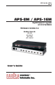
WTI Part No. 13511 Rev. B APS-8M / APS-16M Asynchronous Port Switches with Internal Modem Firmware Version 4.
Warnings and Cautions: INSTALLATION INSTRUCTIONS Secure Racking If Secure Racked units are installed in a closed or multi-unit rack assembly, they may require further evaluation by Certification Agencies. The following items must be considered. 1. The ambient within the rack may be greater than room ambient. Installation should be such that the amount of air flow required for safe operation is not compromised. The maximum temperature for the equipment in this environment is 45°C.
APS-8M / APS-16M Asynchronous Port Switches; User’s Guide No Serviceable Parts Inside; Authorized Service Personnel Only Do not attempt to repair or service this device yourself. Internal components must be serviced by authorized personnel only. • Shock Hazard - Do Not Enter Disconnect Power If any of the following events are noted, immediately disconnect the unit from the outlet and contact qualified service personnel: ii 1. If the power cord becomes frayed or damaged. 2.
Table of Contents 1. Introduction . . . . . . . . . . . . . . . . . . . . . . . . . . . . . . . . . . . . . . . . . . . . . . . . . . . . . . . . . . 1-1 2. Unit Description . . . . . . . . . . . . . . . . . . . . . . . . . . . . . . . . . . . . . . . . . . . . . . . . . . . . . . . 2-1 2.1. Front Panel . . . . . . . . . . . . . . . . . . . . . . . . . . . . . . . . . . . . . . . . . . . . . . . . . . . . . . . 2-1 2.2. Back Panel . . . . . . . . . . . . . . . . . . . . . . . . . . . . . . . . . . . . .
APS-8M / APS-16M Asynchronous Port Switches; User’s Guide 9. Saving and Restoring Configuration Parameters . . . . . . . . . . . . . . . . . . . . . . . . . . . . 9-1 9.1. Sending Parameters to a File . . . . . . . . . . . . . . . . . . . . . . . . . . . . . . . . . . . . . . . . . 9-1 9.2. Restoring Saved Parameters. . . . . . . . . . . . . . . . . . . . . . . . . . . . . . . . . . . . . . . . . . 9-2 10. Upgrading APS-8/16M Firmware . . . . . . . . . . . . . . . . . . . . . . . . . . . . . . . . . . . .
1. Introduction WTI’s APS-8M and APS-16M Asynchronous Port Switches allow reliable, high-speed connections between PCs, modems, and other devices using dissimilar baud rates, parity, and flow control. The APS-8M and APS-16M support communication at speeds up to 115.2 Kbps, and feature full RTS/CTS hardware handshaking and a 33.6K V.34 internal modem. Lightening-swift data throughput and full flow control make the APS-8M and APS-16M the perfect data switches for today’s high speed communications applications.
APS-8M / APS-16M Asynchronous Port Switches; User’s Guide Modem Communication The APS-8M and APS-16M can both be controlled by a local PC that communicates with the unit via cable, or controlled remotely via external modem. Hyperterminal (or another communications program) is used to send commands to connect ports or display status. Configuration Backup Once you have configured the APS-8M or APS-16M to fit your application, parameters and options can be saved to an ASCII text file on your PC.
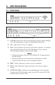
2. Unit Description 2.1. Front Panel Figure 2.1: Instrument Front Panel (Model APS-8M) Figure 2.2: Instrument Front Panel (Model APS-16M) CLEAR: Restarts the APS-8/16M operating program without changing user-selected parameter settings or breaking port connections. ON: Lights when AC Power is applied. SET: Used to Initialize the APS-8/16M to factory defaults. To initialize, press and hold both the SET and CLEAR buttons, release only the CLEAR button, and then release the SET button.
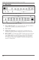
APS-8M / APS-16M Asynchronous Port Switches; User’s Guide 2.2. Back Panel Figure 2.3: Instrument Back Panel (Model APS-8M) Figure 2.4: Instrument Back Panel (Model APS-16M) Power Cable Receptacle: AC powered units only. DC units include a terminal block assembly as described in Section 4.1.2. Power Switch Modem Port (Line Port): For connection to your phone line. For information regarding modem configuration, please refer to Section 6.
3. Getting Started This Quick Start Guide describes a simplified installation procedure for the APS-8M and APS-16M hardware, which will allow you to communicate with the unit in order to demonstrate basic features and check for proper operation. Note that this Quick Start Guide does not provide a detailed description of unit configuration, or discuss advanced operating features in detail.
APS-8M / APS-16M Asynchronous Port Switches; User’s Guide 3.3. Communicating with the APS-8/16M The APS-8/16M command mode allows you to check unit status, change configuration parameters and connect and disconnect ports (including the Modem Port.) 1. Access Command Mode: a) Via Local PC: Start your communications program and then press [Enter]. The "APS>" command prompt should appear.
Getting Started PORT STATUS: APS-M, Version 3.
APS-8M / APS-16M Asynchronous Port Switches; User’s Guide 5. Exit Command Mode: At the "APS>" command prompt, type /X and press [Enter]. The APS-8/16M will exit command mode. This completes the Quick Start Guide for the APS-8/16M. Prior to placing the unit into operation, please proceed to Sections 4 and 5 for complete installation and configuration procedures.
4. Hardware Installation 4.1. Connecting Power to the APS Unit The APS-8/16M is available in both AC and DC powered versions. When connecting power, proceed as follows: CAUTION: • Before attempting to install this unit, please review the warnings and cautions listed at the front of the user's guide. • This device should only be operated with the type of power source indicated on the instrument nameplate. If you are not sure of the type of power service available, please contact your local power company. 4.
APS-8M / APS-16M Asynchronous Port Switches; User’s Guide 4.2. Connect a Telco Line to the Modem Port Use a standard RJ-11 cable to connect your Telco outlet to the Modem (Line) Port, located on the APS-8/16M back panel. Note that the APS-8M sees the internal modem as Port 8, and the APS-16M sees the internal modem as Port 17. 4.3. Connecting Devices to the APS Serial Ports The serial RS232 Ports are standard DB9 connectors, configured as DTE Ports, and are similar to a standard serial port on a PC.
5. Configuration 5.1. Access to the APS-8/16M Command Mode When the APS-8/16M command mode is active, commands can be invoked to select parameters, and connect or disconnect ports. Note: • Command mode cannot be accessed from a Buffer Mode Port, Passive Mode Port, or any port that is currently connected to another APS-8/16M port. • Configuration commands are not available at any port where the Supervisor Mode has been disabled.
APS-8M / APS-16M Asynchronous Port Switches; User’s Guide 5.2. System SetUp Ports Ports 1 and 2 are designated as System SetUp Ports, and will therefore, always permit password protected access to Supervisor Mode. In order to ensure that access to command functions is always available, Ports 1 and 2 cannot be configured as Buffer Mode or Passive Mode Ports (Buffer Mode Ports and Passive Mode Ports are not able to access command mode.
Configuration Notes: • If you do not define at least one password that permits access to Supervisor Mode, then Supervisor Level commands will be available to all ports, and port access and configuration functions will not be password protected. • If you wish to restrict users from changing APS-8/16M configuration parameters or connecting to restricted ports, you must define at least one password that permits access to Supervisor Mode as described in Section 5.4.1.
APS-8M / APS-16M Asynchronous Port Switches; User’s Guide SYSTEM PARAMETERS: 1. 2. 3. 4. 5. Site-ID: Password on Dial Back: Dial Back Attempts: Dial Back Delay: Edit Password Directory (undefined) Off 3 30 Secs Enter: # to change, exit ... Figure 5.1: The System Parameters Menu (/F) To define System Parameters, you must first access command mode, and then type /F [Enter] to display the System Parameters Menu (Figure 5.1.) The System Parameters Menu allows you to define the following: 1.
Configuration EDIT PASSWORD DIRECTORY: 1. 2. 3. 4. Add Name/Password Edit/Delete from List Edit/Delete from Search Delete Entire Directory Enter: # to select, for previous menu ... Figure 5.2: The Edit Password Directory Menu 5.4.1. The Password Directory APS-8/16M passwords are defined using the "Edit Password Directory" menu, which is accessed via the System Parameters menu (/F).
APS-8M / APS-16M Asynchronous Port Switches; User’s Guide ADD NAME/PASSWORD: 1. 2. 3. 4. 5. 6. 7. Name: Password: Dial Back #: Dial Back Mode: Supervisor Mode: Port Access: Save Entry (undefined) (undefined) (undefined) Off Off None Enter: # to select, for previous menu ... Figure 5.3: The Add Name/Password Menu (Defaults Shown) 5.4.1.1. Adding Passwords The "Add Name/Password" menu is used to create new user accounts and add passwords to the password directory.
Configuration EDIT/DELETE NAME/PASSWORD: 1. 2. 3. 4. 5. 6. 7. 8. Name: Password: Dial Back #: Dial Back Mode: Supervisor Mode: Port Access: Save Entry Delete Entry test (defined) 5556789 On On 1, 2, 3, 4, 5, 6, 7, 8 Type: “<” previous entry, “>” next entry, to selection, to abort ... Figure 5.4: The Edit/Delete Name/Password Menu (Sample Values Shown) 6. Port Access: The ports that this password will be allowed to create connections with.
APS-8M / APS-16M Asynchronous Port Switches; User’s Guide 5.4.1.3. Deleting the Entire Password Directory The Edit Password Directory menu (Figure 5.2) also allows you to delete the entire password directory, rather than accessing each individual password and deleting them one at a time. To delete the Password Directory and clear all passwords, activate the "Edit Password Directory" Menu as describe in Section 5.4.1, type 4 and press [Enter].
Configuration 3. Edit Password Directory: From the System Parameters Menu, type 5 and press [Enter] to display the Edit Password Directory Menu. At this point, you may either define new passwords that use the Dial Back Function, or alter existing passwords to include the Dial Back Function. The following parameters should be defined in the Add Name/Password Menu or Edit/Delete Password/Name Menu: • Item 3, Dial Back #: The number that will be called when a Dial Back is performed.
APS-8M / APS-16M Asynchronous Port Switches; User’s Guide 5.5. Port Configuration 5.5.1. Configuration Conventions When responding to prompts, invoking commands, and selecting items from port configuration menus, note the following: • To select an item from a Port Configuration menu, key in the number for the item and press [Enter]. • To clear an item in a Port Configuration menu, enter the number for the desired item and press [Enter]. When the prompt appears, press [Space] and then press [Enter].
Configuration 5.5.2. Port Modes The APS-8/16M offers four different port operation modes; Any-to-Any Mode, Passive Mode, Buffer Mode, and Modem Mode. The Port Modes function as follows: • Any-to-Any Mode: Allows communication between connected ports. Any-to-Any Mode Ports can be connected to other Any-to-Any, Passive, Buffer, or Modem Mode Ports by accessing command mode and invoking the /C command (see Section 8.1.1).
APS-8M / APS-16M Asynchronous Port Switches; User’s Guide PORT PARAMETERS #01: 1. 2. 3. 4. 5. 6. 7. 8. 9. 10. 11. 12. 13. 14. Port Name: Baud Rate: Bits/Parity: Stop Bits: Handshake Mode: Port Mode: 64.
Configuration The Port Configuration menu offers the following options: 1. Port Name: (Up to 16 characters) Assigns a name to the port. • (APS-8M Defaults: Ports 1 through 7 = undefined; Port 8 = "Internal_Modem"). • (APS-16M Defaults: Ports 1 through 16 = undefined; Port 17 = "Internal_Modem"). 2. Baud Rate: Selects the baud rate for the port. Can be set to any standard rate from 300 bps to 115.2K bps. (Default = 9600 bps) 3. Bits/Parity: (Default = 8-None). 4. Stop Bits: (Default = 1). 5.
APS-8M / APS-16M Asynchronous Port Switches; User’s Guide PORT PARAMETERS #03: 1. 2. 3. 4. 5. 6. 7. 8. 9. 10. 11. 12. 13. 14. Port Name: Baud Rate: Bits/Parity: Stop Bits: Handshake Mode: Port Mode: 61. Reset String: 62. Init String: 63.
Configuration 7. Supervisor Mode: Permits or denies access to Supervisor Mode at this port. When enabled (Permit), and a password that permits Supervisor Mode is entered, the port will allow access to Supervisor Mode commands. When disabled (Deny), the port will not enter Supervisor Mode, even when a password that normally permits access to Supervisor Mode is entered. (Default = Permit). Note: The Supervisor Mode cannot be disabled at Ports 1 or 2. 8.
APS-8M / APS-16M Asynchronous Port Switches; User’s Guide 10. Timeout Disconnect: Enables and selects the Timeout Period for this port. If enabled, and the port does not receive or transmit data for the specified Timeout Period, the port will disconnect. In Any-to-Any Mode, Passive Mode, or Buffer Mode, the default setting for this item is "OFF". When the port is set for Modem Mode, the default setting for this item is 15 minutes.
Configuration 5.5.4. The Invalid Access Lockout Feature When properly configured and enabled, the Invalid Access Lockout feature will watch all login attempts made at a given port. If the port exceeds the selected number of invalid attempts, then that port will be automatically disabled for a user-defined length of time. Note that when an Invalid Access Lockout occurs, you can either wait for the Lockout Duration period to elapse, or issue the /UL command to instantly unlock all ports.
APS-8M / APS-16M Asynchronous Port Switches; User’s Guide COPY PORT PARAMETERS: 1. 2. 3. 4. 5. 6. 7. 8. 9. 10. 11. 12. 13. 14. Port Name: Baud Rate: Bits/Parity: Stop Bits: Handshake Mode: Port Mode: 64. DTR Output: Supervisor Mode: Logoff Character: Sequence Disconnect: Timeout Disconnect: Response Type: Command Echo: Accept Break: Invalid Access Lockout: (Note: ports 1 & 2 will NOT have restricted values changed.
Configuration To select common parameters for all APS-8/16M RS-232 ports, proceed as follows: 1. Access command mode. If the password prompt is displayed, key in a password that permits Supervisor Mode. 2. At the command prompt, type /CP and press [Enter], the menu shown in Figure 5.7 will be displayed. 3. Selecting Parameters: To select parameters to be copied, key in the number for the desired parameter, press [Enter], then follow the instructions in the submenu.
APS-8M / APS-16M Asynchronous Port Switches; User’s Guide 5-20
6. The Internal Modem This section lists commonly used AT commands for the APS-8/16M’s internal modem, and briefly describes the procedure for communicating with the internal modem. Please note that although APS-8/16M includes an internal modem, any APS-8/16M RS232 port can also be configured for connection to an external modem. 6.1. Communicating with the Internal Modem To communicate with the APS-8/16M’s internal modem, proceed as follows: 1. Access the APS-8/16M command mode as described in Section 5.1.
APS-8M / APS-16M Asynchronous Port Switches; User’s Guide 6.2. Common AT Commands This section lists some of the most commonly used AT commands for the APS-8/16M’s internal modem. For a complete listing of all available AT Commands and S-Registers, please refer to the "MT5634 Modem AT Command Set" document at http://www.wti.com/guides/guidarch.htm. Notes: • Type commands in either upper or lower case. Do not use a combination of upper and lower case characters. • Use the Backspace key to delete errors.
The Internal Modem Command Function/Options Data Terminal Ready (DTR) Control. &Dn &D0 Modem ignores true status of DTR signal and responds as if it is always on. &D1 If DTR drops while in online data mode, the modem enters command mode, issues an OK, and remains connected. * &D2 If DTR drops while in online data mode, the modem hangs up. If the signal is not present, the modem will not answer or dial. &D3 If DTR drops, the modem hangs up and resets as if an ATZ command had been issued.
APS-8M / APS-16M Asynchronous Port Switches; User’s Guide Command Function/Options Information Request In I0 Display default speed and controller firmware version. I1 Calculate and display ROM checksum (e.g., 12AB.) I2 Check ROM and verify the checksum, displaying OK or ERROR I3 Display default speed and controller firmware version. I4 Display firmware version for data pump (e.g., 94.) I5 Display the board ID: software version, hardware version, and country ID. I9 Display the country code.
7. The Status Screens The APS-8/16M Status Screens display the connection status and communication parameters for the RS-232 ports. Basically, There are four different status screens; The Port Status screen (/S), the Port Diagnostics screen (/SD), the Port Parameters screens (/W), and the View Password Directory screen. 7.1. The Port Status Screen (/S) The Port Status Screen lists the general status of the RS-232 ports.
APS-8M / APS-16M Asynchronous Port Switches; User’s Guide As shown in Figure 7.1, The Port Status Screen lists the following: • Name: The user-defined name for each port. • Command Access: Indicates if the corresponding port has been disabled by the Invalid Access Lockout feature. If this column reads "Locked", then the defined number of invalid access attempts for this port has been exceeded, and the port has been locked in order to prevent further access attempts.
The Status Screens PORT DIAGNOSTICS: APS-M, Version 3.
APS-8M / APS-16M Asynchronous Port Switches; User’s Guide PORT PARAMETERS #01: 1. 2. 3. 4. 5. 6. 7. 8. 9. 10. 11. 12. 13. 14. Port Name: Baud Rate: Bits/Parity: Stop Bits: Handshake Mode: Port Mode: 64. DTR Output: Supervisor Mode: Logoff Character: Sequence Disconnect: Timeout Disconnect: Response Type: Command Echo: Accept Break: Invalid Access Lockout: (undefined) 9600 8-None 1 RTS/CTS Any-to-Any Pulse Permit ^X One Character Only Off Verbose On Yes Off APS> Figure 7.
The Status Screens Name Password Dial Back # DB SA ------------------------------------------------------------------------------admin (defined) 5556789 On On drafting (defined) (undefined) Off Off engineering (defined) (undefined) Off On finance (defined) 5559900 On Off hr (defined) (undefined) Off Off manufacturing (defined) (undefined) Off Off marketing (defined) 5551234 On Off sales (defined) 5559876 On Off service (defined) 5554321 Off Off test (defined) 5556789 On On Reached End of Directory. APS> Figure 7.
APS-8M / APS-16M Asynchronous Port Switches; User’s Guide 7-6
8. Operation 8.1. Any-to-Any Mode Any-to-Any Mode Ports can be connected to other Any-to-Any, Passive, Buffer, or Modem Mode Ports by accessing command mode and issuing the /C Command. All ports can be configured for the Any-to-Any Mode. 8.1.1. Port Connection and Disconnection The APS-8/16M provides communication between devices without the requirement that both devices use the same communication parameters. This allows you to connect devices that use dissimilar baud rates, parity, handshake, and etc.
APS-8M / APS-16M Asynchronous Port Switches; User’s Guide To connect ports, proceed as follows: 1. Access command mode as described in Section 5.1. If the Password Prompt is displayed, enter a password that permits Supervisor Mode. 2. Invoke the /C command to connect the desired ports. a) Resident Connect: To connect your resident port to another port, type /C xx [Enter]. Where xx is the number or name of the port you want to connect.
Operation To disconnect ports, proceed as follows: 1. 2. Resident Disconnect: Disconnects your resident port from another port. For example, if you are communicating via Port 3, and Port 3 is connected to Port 4, a Resident Disconnect would be used to disassociate the two ports. The APS-8/16M offers two different Resident Disconnect command formats; the One Character Format and the Three Character Format (for more information, please refer to Section 5.5.3.
APS-8M / APS-16M Asynchronous Port Switches; User’s Guide 3. No Activity Timeout: Providing the Timeout Disconnect feature is enabled at either connected port, a No Activity Timeout can disconnect Resident Ports, or Third Party Ports. a) RS232 Ports: To configure the Timeout Disconnect Feature for the RS232 Ports, invoke the /P command to display the Port Configuration Menu for the desired port as described in Section 5.5.3. Option 10 enables and defines the Timeout Disconnect Feature.
Operation 6. Your port will be connected to the first available port in the group. If all ports are presently connected, the APS-8/16M will respond with a "BUSY" message. 7. It is only necessary to enter enough letters of the port name to differentiate Hunt Group ports from other ports. Type an asterisk (*) to represent the remaining characters in the port name.
APS-8M / APS-16M Asynchronous Port Switches; User’s Guide 8.2. Passive Mode Passive Mode Ports function the same as Any-to-Any Mode Ports, but do not allow access to command mode. A Passive Mode Port can communicate with other ports, but cannot enter command mode, and therefore cannot invoke commands to redefine port parameters, display status, and etc.
Operation 8.3.1. Reading Data from Buffer Mode Ports To retrieve data from Buffer Mode Ports, you must first determine which port buffers contain data. To check port buffers for stored data, access command mode and type /S [Enter] to display the Port Status Screen.
APS-8M / APS-16M Asynchronous Port Switches; User’s Guide 8.3.2. Port Buffers The Status Screen lists the amount of Buffer Memory currently used by each port. The APS-8/16M uses buffer memory in two different ways, depending on the user-selected port mode. • Any-to-Any, Passive, and Modem Mode Ports: When two ports are communicating at dissimilar baud rates, the buffer memory prevents data overflow at the slower port. • Buffer Mode Ports: Stores data received from connected devices.
Operation Notes: • When a Modem Mode Port exits command mode, or the DCD line is lost while command mode is active, the APS-8/16M will pulse the DTR line to the modem. The unit will then send the user-defined modem command strings to make certain the modem is properly disconnected and reinitialized. • All APS-8/16M RS232 ports can use both the unit’s internal modem and external modem(s) installed at another RS232 port, providing that the port password allows access to the desired modem port.
APS-8M / APS-16M Asynchronous Port Switches; User’s Guide 8-10
9. Saving and Restoring Configuration Parameters After the APS-8/16M has been properly configured, parameters can be downloaded and saved as an ASCII text file. Later, if the configuration is accidentally altered, the file with the saved parameters can be uploaded to automatically reconfigure the unit without the need to manually re-assign each parameter. Saved parameters can also be uploaded to other identical APS-8/16M units.
APS-8M / APS-16M Asynchronous Port Switches; User’s Guide 9.2. Restoring Saved Parameters This section describes the procedure for using your communications program to send stored parameters to the APS-8/16M. 1. Start your communications program and access the APS-8/16M command mode; if the password prompt is displayed, enter a password that permits access to Supervisor Mode. 2. Configure your communications program to upload an ASCII text file. 3.
10. Upgrading APS-8/16M Firmware When new, improved versions of the APS-8/16M operating firmware become available, the /UF (Upgrade Firmware) function can be used to update the APS-8/16M unit to the new firmware version. Updates can be uploaded to the unit via SetUp Ports one and two, or via the Internal Modem Port. To install a firmware update, proceed as follows: Note: All other ports will be disabled during the firmware upgrade procedure. 1. Obtain the update file.
APS-8M / APS-16M Asynchronous Port Switches; User’s Guide 4. Use your communication program’s (e.g. HyperTerminal’s) upload function to transfer the upgrade firmware to the unit. Select ASCII file format, and then specify the filename and directory location where the firmware upgrade file resides. Note: The Upload function will time-out after one minute of inactivity. If the function times out, type 1 and press [Enter] to continue, or press [Esc] to abort. 5.
11. Command Reference Guide 11.1. Command Conventions The commands described in this section conform to the following conventions: • Slash Character: Most APS-8/16M commands begin with the Slash Character (/). • Apply Command to All Ports: When the asterisk character is entered as the argument of the /D command (Disconnect Port), or the /E command (Erase Buffer) the command will be applied to all ports. For example, to erase all port buffers, type /E * [Enter].
APS-8M / APS-16M Asynchronous Port Switches; User’s Guide 11.2. Command Response When commands are sent to the APS-8/16M, the unit can respond with either verbose (English Text) or terse messages (numeric / abbreviated). In the default state, all ports will send verbose command responses. After the unit is installed and configured, the port configuration command (/P) can specify an individual response format for each port.
Command Reference Guide 11.3.
APS-8M / APS-16M Asynchronous Port Switches; User’s Guide 11.4. Command Set This section provides more detailed information on all APS-8/16M commands, sorted alphabetically by name. [Enter] Enter Command Mode In order to set parameters or connect ports, you must first access command mode as described in Section 5.1. When command mode is inactive (port asleep), the port will only respond when the [Enter] key is pressed without any characters preceding it.
Command Reference Guide /C Connect Establishes a bidirectional connection between two ports. For more information and command line examples, please refer to Section 8.1. There are two types of port connections: • Resident Connect: If the /C command specifies one port name or number, your resident port will be connected to the specified port. • Third Party Connect: If the /C command specifies two port names or numbers, the unit will connect the two ports indicated.
APS-8M / APS-16M Asynchronous Port Switches; User’s Guide /D Third Party Disconnect Invoke the /D command at your resident port to disconnect two other ports. The /D command cannot be used to disconnect your resident port. To disconnect your resident port, issue the Resident Disconnect Sequence or wait for the Timeout Period to elapse (if enabled). Availability: Supervisor Mode Only Format: /D[/Y] [x] [Enter] Where: /Y (Optional) suppresses the "Sure?" prompt.
Command Reference Guide /F Set System Parameters Displays a menu which is used to define the Site ID message and other global parameters. Also allows access to the "Add Password" function. For more information, please refer to Section 5.4. Availability: Supervisor Mode Only Format: /F [Enter] Response: Displays System Parameters Menu /H Help Displays a Help Screen, which lists all APS-8/16M commands along with a brief description of each command.
APS-8M / APS-16M Asynchronous Port Switches; User’s Guide /P Set RS232 Port Parameters Displays a menu which allows the user to select options and parameters for the selected port. Section 5.5.3 describes the procedure for defining port parameters. Availability: Supervisor Mode Only Format: /P [x] [Enter] Where x is the number or name of the port to be configured. If the port number or name is not specified, the APS-8/16M will display the configuration menu for your resident port.
Command Reference Guide /U Save Parameters Sends configuration parameters to an ASCII text file as described in Section 9. Availability: Supervisor Mode Only Format: /U [Enter] Response: The APS-8/16M will send a series of command lines. /UF Upgrade Firmware When new versions of the APS-8/16M operating firmware become available, this command is used to update the existing firmware as described in Section 10. Note that this command will only function at the Internal Modem Port and at Setup Ports One and Two.
APS-8M / APS-16M Asynchronous Port Switches; User’s Guide /W Display Port Parameters (Who) Displays detailed configuration information for an individual port. Ports with User Level command capability cannot display parameters for other ports. If you have logged into command mode using a port and password that permit Supervisor Mode, the /W command can display information for any APS-8/16M port.
A. RS232 Port Interface Figure A.1: RS232 Port Hardware DCD and DTR hardware lines function as follows: 1. 2. When connected: a) If either port is set for Modem Mode, the DTR output at either port reflects the DCD input at the other end. b) If neither port is set for Modem Mode, DTR output is held high (active). When not connected: a) If the port is set for Modem Mode, upon disconnect DTR output is pulsed for 0.5 seconds and then held high.
APS-8M / APS-16M Asynchronous Port Switches; User’s Guide B. Specifications RS232 Port Interface: • APS-8M & APS-8M-DC: Seven (7) RS232 serial inputs use DB9 connectors configured as DTE ports. • APS-16M & APS-16M-DC: Sixteen (16) RS232 serial inputs use DB9 connectors configured as DTE ports. Internal Modem Interface: RJ11 connectors for connection to your telco line Coding: Asynchronous, 7/8 bits ASCII. Parity: Even, Odd, None Stop Bits: 1 or 2. Data Rate: 300 to 115.2K bps (standard rates).
Appendices C. Customer Service Customer Service hours are from 8:00 AM to 5:00 PM, PST, Monday through Friday. When calling, please be prepared to give the name and make of the unit, its serial number and a description of its symptoms. If the unit should need to be returned for factory repair it must be accompanied by a Return Authorization number from Customer Service.
APS-8M / APS-16M Asynchronous Port Switches; User’s Guide D. Trademark and Copyright Information WTI and Western Telematic are trademarks of Western Telematic Inc.. All other product names mentioned in this publication are trademarks or registered trademarks of their respective companies. Information and descriptions contained herein are the property of Western Telematic Inc..
Appendices E. Regulatory Statements FCC Part 15 Regulation This equipment has been tested and found to comply with the limits for a Class A digital device, pursuant to part 15 of the FCC Rules. These limits are designed to provide reasonable protection against harmful interference when the equipment is operated in a commercial environment.
APS-8M / APS-16M Asynchronous Port Switches; User’s Guide If trouble is experienced with this equipment, for repair or warranty information, please contact Western Telematic, Inc. at 1-800-854-7226. If the equipment is causing harm to the telephone network, the telephone company may request that you disconnect the equipment until the problem is resolved. Connection to party line service is subject to state tariffs.
Index Accept Break Activity LEDs AC Powered Units Adding Passwords Add Name/Password Dial Back Number Name Password Port Access Supervisor Mode Any-to-Any Mode AT Commands Baud Rate Bits Breaks Buffer Mode Port Buffers Reading Data A B C CLEAR Button Command Echo Command Mode Access Local Modem Command Reference Guide Command Response Command Set Command Summary Configuration Connecting Ports Connecting Power Connect Command Copying Parameters Copy Parameters Customer Service D Data Bits DCD Indicator
APS-8M / APS-16M Asynchronous Port Switches; User’s Guide Name No Activity Timeout N O One Character Disconnect ON Indicator Operation P 5-6 8-4 5-15, 8-3 2-1 8-1 to 8-9 Parameters Saving and Restoring 9-1 to 9-2 Parity 5-13 Passive Mode 5-1, 5-11, 8-6 Passwords 5-2 to 5-4 Adding 5-6 to 5-7 Editing and Deleting 5-7 to 5-8 Password Directory 5-4 to 5-6, 11-9 Add Name/Password 5-5 to 5-6 Delete Entire Directory 5-5 Deleting Entire 5-8 Edit/Delete from List 5-5 to 5-6 Edit/Delete from Search 5-5 Password
Index T Terminal Block Terse Response Third Party Connections Third Party Disconnect Three Character Disconnect Timeout Timeout Disconnect Unlocking Ports Unlock Ports Upgrade Firmware Upgrading Firmware User Name Verbose Response U V W Warnings and Cautions Who Command 4-1 5-16, 11-2 8-1 8-3, 11-6 5-15, 8-3 8-4 5-16 5-17 11-9 11-9 10-1 to 10-2 5-6 5-16, 11-2 ii 11-10 Index-3
APS-8M / APS-16M Asynchronous Port Switches; User’s Guide Index-4
5 Sterling • Irvine • California 92618 (949) 586-9950 • Toll Free: 1-800-854-7226 Fax: (949) 583-9514 • http://www.wti.