
User Manual


22 | Westinghouse Portable Power
1
2
3
4
5
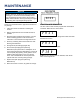
Figure 21
(1) Push Rod, (2) Feeler Gauge Area
(3) Rocker Arm, (4) Jam Nut, (5) Adjusting Nut
Standard Valve Lash
Intake Valve Exhaust Valve
Valve Lash
0.0035 ± 0.0043 in
(0.09 ± 0.11 mm)
0.0043 ± 0.0051 in
(0.11 ± 0.13 mm)
Bolt Torque
8-12N.m 8-12N.m
6. If an adjustment is required, hold the adjusting nut and
loosen the jam nut.
7. Turn the adjusting nut to obtain the correct valve lash.
When the valve lash is correct, hold the adjusting nut
and tighten the jam nut to 106 in-lb (12 N•m).
8. Recheck the valve lash after tightening the jam nut.
9. Perform this procedure for both the intake and exhaust
valves.
10. Install the rocker arm cover, gasket and spark plug.
CLEANING THE INVERTER
It is important to inspect and clean the inverter before every
use.
Clean All Engine Air Inlet and Outlet Ports – Make sure
all engine air inlet and outlet ports are clean of any dirt and
debris to ensure the engine does not run hot.
STORAGE
WARNING
Never store an inverter with fuel in the
tank indoors or in a poorly ventilated
area where the fumes can come in
contact with an ignition source such
as a: 1) pilot light of a stove, water
heater, clothes dryer or any other gas
appliance; or 2) spark from an electric
appliance.
MAINTENANCE
Figure 20: Remove spark arrestor
8. Using a wire brush, remove any dirt and debris that
may have collected on the spark arrestor screen.
9. If the spark arrestor screen shows signs of wear
(rips, tears or large openings in the screen), replace
the spark arrestor screen.
10. Install the spark arrestor components in the
following order:
a. Place spark arrestor screen over the muer
exhaust pipe. Push on the screen until it fully
bottoms out.
b. Place the spark arrestor band clamp over the
screen and tighten with a screwdriver
11. Replace the muer cover and the inverter cover
that you removed in step 4.
CHECKING AND ADJUSTING VALVE LASH
CAUTION
Checking and adjusting valve lash
must be done when the engine is cold.
1. Remove the rocker arm cover and carefully remove
the gasket. If the gasket is torn or damaged, it must
be replaced.
2. Remove the spark plug so the engine can be
rotated more easily.
3. Rotate the engine to top dead center (TDC) of the
compression stroke. Looking through the spark
plug hole, the piston should be at the top.
4. Both the rocker arms should be loose at TDC on
the compression stroke. If they are not, rotate the
engine 360°.
5. Insert a feeler gauge between the rocker arm and
the push rod and check for clearance (see Figure
21). See table below for valve lash specications