California Proposition 65 Warning California Proposition 65 Warning The engine exhaust from this product contains chemicals known to the state of California to cause cancer, birth defects or other reproductive harm. Certain components in this product and its related accessories contain chemicals known to the state of California to cause cancer, birth defects or other reproductive harm. Wash hands after handling.
CONGRATULATIONS ON OWNING A WESTINGHOUSE GENERATOR ! DANGER This manual contains important instructions for operating this generator. For your safety and the safety of others, be sure to read this manual thoroughly before operating the generator. Failure to properly follow all instructions and precautions can cause you and others to be seriously hurt or killed.
TABLE OF CONTENTS CONGRATULATIONS ON OWNING A WESTINGHOUSE GENERATOR .........................................................3 For Your Records: .........................................................................................................................................3 Product Registration .....................................................................................................................................3 Product Registration Form .............................................
TABLE OF CONTENTS PRODUCT WARRANTY APPLICATIONS AND PRODUCT WARRANTY PERIODS ................................36 CONSUMER APPLICATION ................................................................................................................36 COMMERCIAL APPLICATION ............................................................................................................36 NON-WARRANTABLE APPLICATIONS ..............................................................................................
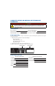
SAFETY SAFETY DEFINITIONS The words DANGER, WARNING, CAUTION and NOTICE are used throughout this manual to highlight important information. Be certain that the meanings of these alerts are known to all who work on or near the equipment. ! This safety alert symbol appears with most safety statements. It means attention, become alert, your safety is involved! Please read and abide by the message that follows the safety alert symbol.
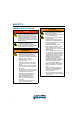
SAFETY GENERAL SAFETY RULES ! DANGER Never use the generator in a location that is wet or damp. Never expose the generator to rain, snow, water spray or standing water while in use. Protect the generator from all hazardous weather conditions. Moisture or ice can cause a short circuit or other malfunction in the electrical circuit. Never operate the generator in an enclosed area. Engine exhaust contains carbon monoxide. Only operate the generator outside and away from windows, doors and vents.
SAFETY ! WARNING Never operate the generator if powered items overheat, electrical output drops, there is sparking, flames or smoke coming from the generator, or if the receptacles are damaged. ! Never use the generator to power medical support equipment. Always remove any tools or other service equipment used during maintenance from the generator before operating. NOTICE Never modify the generator.
SAFETY SAFETY LABELS AND DECALS 1 2 3 5 4 1 2 4 3 Figure 1 10 5
SAFETY 2 3 1 4 5 1 2 5 3 Class F 4 Figure 2 11
UNPACKING UNPACKING THE GENERATOR 1 ! CAUTION Always have assistance when lifting the generator. The generator is heavy; lifting it could cause bodily harm. ! Avoid cutting on or near staples to prevent personal injury. 4 2 Tools required – box cutter or similar device. 1. Carefully cut the packing tape on top of the carton. 2. Fold back top flaps to reveal the manual. 3 3. Remove the Wheel Kit Accessories cardboard box. 4. Carefully cut two sides of the carton to remove the generator.
ASSEMBLY 1. Place generator on a flat surface. ASSEMBLY Before assembling the generator, review Safety on page 7 and the following safety messages. 2. Using a block of wood, raise and support the back of the generator. 3. Install the mounting foot to the frame using M8 flange bolts and nuts (see Figure 4). ! CAUTION 1 Never lift the generator without assistance. The generator is heavy and lifting without assistance could result in personal injury.
ASSEMBLY INSTALLING THE BATTERY 2 ! WARNING To avoid electric shock: • ALWAYS connect the positive (+) battery cable (red boot) first when connecting battery cables. • ALWAYS disconnect the negative (-) battery cable (black boot) first when disconnecting battery cables. • NEVER connect the negative (-) battery cable (black boot) to the positive (+) post on the battery. • NEVER connect the positive (+) battery cable (red boot) to the negative (-) post on the battery.
FEATURES GENERAL GENERATOR FEATURES 2 1 5 4 3 Figure 7 1 - Engine Control Switch: Turns the engine on and off. 4 - Oil Dipstick: Remove the dipstick to check the engine oil. 2 - Control Panel: Contains the circuit breakers and outlets. 5 - Choke Knob: Pull out to the ON position to start the engine, and push into the OFF position once the engine is running. 3 - Battery: Used for starting the generator.
FEATURES 1 2 3 4 5 6 Figure 8 16 1 - Fuel Gauge: Indicates fuel level. 4 - Oil Fill Cap: Remove to add engine oil. 2 - Fuel Shutoff Valve: Controls the flow of fuel to the engine. 5 - Spark Plug Boot (Wire): Must be removed when servicing the engine or the spark plug. 3 - Air Cleaner Cover: Must remove to service the air cleaner. 6 - Muffler: Avoid contact until the engine is cooled down.
FEATURES CONTROL PANEL FEATURES 1 2 3 4 5 6 9 8 7 Figure 9 – Control Panel Features 1 - 120-Volt, 20-Amp Duplex GFCI Outlets (5-20R): Each outlet is capable of carrying a maximum of 20 amps on a single receptacle or a combination of both receptacles. 2 - 20-Amp Circuit Breakers: Each circuit breaker limits the current that can be delivered through the 120-volt duplex outlets to 20 amps. 3 - 120/240-Volt, 50-Amp Twist Lock Outlet: Outlet can supply either 120V or 240V output.
OPERATION BEFORE STARTING THE GENERATOR Before starting the generator, review Safety on page 7. Location Selection – Before starting the generator, avoid exhaust and location hazards by verifying: x You have selected a location to operate the generator that is outdoors and well ventilated. x You have selected a location with a level and solid surface on which to place the generator. x You have selected a location that is at least 6 feet (1.
OPERATION ! WARNING Be sure the generator is properly connected to earth ground before operating. The generator must be grounded to prevent electrical shock due to faulty appliances. POWER CORD Using Extension Cords Westpro Power Systems assumes no responsibility for the content within this table. The use of this table is the responsibility of the user only. This table is intended for reference only.
OPERATION Transfer Switch Cord The transfer switch cord, Part No. 210051, is an optional accessory for the portable generator. It is used to connect the 50-amp twist lock outlet of the generator to the transfer switch. If your transfer switch does not come with a transfer switch cord, order the cord from Westpro Power. Figure 12 – Jumper WIre LIFTING STRAP The generator is equipped with a lifting strap. When using the strap to lift the generator, make sure the generator is lifted straight and level. 1.
OPERATION GENERATOR ANCHOR The generator should be used on a flat, level surface whenever possible. If the particular job site requires the generator to be used on uneven terrain, the generator should be anchored. Insert a stake or piece of rebar through the anchor bracket on the frame (see Figure 14). Drive the stake into the ground to secure the generator and prevent it from moving. ADDING / CHECKING ENGINE FLUIDS AND FUEL Before adding/checking engine fluids and fuel, review Safety on page 7.
OPERATION Adding Gasoline to the Fuel Tank ! WARNING Never refuel the generator while the engine is running. Always turn the engine off and allow the generator to cool before refueling. STARTING THE GENERATOR Before starting the generator, review Safety on page 7. Before attempting to start the generator, verify the following: x The engine is filled with engine oil (see Checking Engine Oil on page 26).
OPERATION 3. Move the fuel shutoff valve to the ON position (see Figure 17). NOTICE The engine is equipped with a low oil shutdown switch. If the oil level becomes low, the engine will shut down and will not start until the oil is filled to the proper level. Be sure the engine has the proper oil level before using. Failure to verify that the engine has the proper oil level could result in engine damage. Disconnect all loads from the generator before starting.
OPERATION NOTE: If the engine fails to start after 5 seconds, release the engine control switch. Let the generator sit idle for 15 seconds and then repeat step 5. If the cranking speed drops after each unsuccessful attempt, then the battery may not be adequately charged. Manually start the generator as instructed in Starting the Generator on page 22. NOTE: The generator is equipped with a battery charging feature.
MAINTENANCE MAINTENANCE ! CAUTION Before performing maintenance on the generator, review Safety on page 7 and the following safety messages. Avoid skin contact with engine oil or gasoline. Prolonged skin contact with engine oil or gasoline can be harmful. Frequent and prolonged contact with engine oil may cause skin cancer. Take protective measures and wear protective clothing and equipment. Wash all exposed skin with soap and water.
OPERATION Table 2: Maintenance Schedule - Authorized Westinghouse Service Dealer Performed Maintenance Item Before Every Use After First 20 Hours or First Month of Use After 50 Hours of Use or Every 3 Months After 100 Hours of Use or Every 6 Months After 300 Hours of Use or Every Year Valve Clearance – – – – Check/Adjust Fuel Filter – – – Check/Clean – Idle Speed – – – – Check/Adjust ENGINE OIL MAINTENANCE Engine Oil Specification 1. Only use the engine oil specified in Figure 20. 2.
MAINTENANCE Adding Engine Oil Changing Engine Oil 1. Always operate or maintain the generator on a flat surface. 1. Stop the engine. 2. Stop engine if running. 2. Let engine sit and cool for several minutes (allow crankcase pressure to equalize). 3. Let engine sit and cool for several minutes (allow crankcase pressure to equalize). 3. Place oil pan (or suitable container) under the oil drain plug and oil filter. 4. Thoroughly clean around the oil fill plug. 4.
MAINTENANCE AIR FILTER MAINTENANCE 5. Remove the air cleaner element (see Figure 28). ! WARNING Never use gasoline or other flammable solvents to clean the air filter. Use only household detergent soap to clean the air filter. Inspect and Replace the Air Filter The air filter must be inspected after every 50 hours of use or 3 months (frequency should be increased if generator is operated in a dusty environment). 1. Turn off the generator and let it cool for several minutes if running. 2.
MAINTENANCE SPARK PLUG MAINTENANCE The spark plug must be checked and cleaned after every 100 hours of use or 6 months and must be replaced after 300 hours of use or every year. 1. Stop the generator and let it cool for several minutes if running. 2. Move the generator to a flat, level surface. 3. Remove the spark plug boot by firmly pulling the plastic spark plug boot handle directly away from the engine (see Figure 30).
MAINTENANCE 8. Install the spark plug by carefully following the steps outlined below: a - Carefully insert the spark plug back into the cylinder head. Hand-thread the spark plug until it bottoms out. b - Using the 13/16" spark plug socket wrench provided, turn the spark plug to ensure it is fully seated. Battery Replacement 1. Remove the spark plug wire from spark plug. 2. Loosen and remove the nuts on the battery holddown plate and remove the plate from the support rods (see Figure 34).
MAINTENANCE CLEANING THE ENGINE OIL COOLER 2 1. Remove the screws for the oil cooler (see Figure 36). 1 2 3 1 1 Figure 35 1 - Red Positive (+) Battery Cable 2 - Black Negative (-) Battery Cable NOTICE Dispose of the used battery properly according to the guidelines established by your local or state government. 6. Install the new battery into the generator frame. Figure 36 – Engine Oil Cooler 1 - Oil Cooler Screws 3 - Oil Cooler 2 - Oil Cooler Guard 2.
MAINTENANCE TESTING THE GFCI OUTLETS CLEANING THE GENERATOR 1. Start the generator and allow it to warm up. It is important to inspect and clean the generator before every use. 2. Press the test button on the outlets (see Figure 38). Clean All Engine Air Inlet and Outlet Ports – Make sure all engine air inlet and outlet ports are clean of any dirt and debris to ensure the engine does not run hot (see Figure 39). 2 1 3 Figure 38 – GFCI Outlet Test 1 - Test Button 3 - LED Light 2 - Reset Button 3.
MAINTENANCE STORAGE ! WARNING Never store a generator with fuel in the tank indoors or in a poorly ventilated area where the fumes can come in contact with an ignition source such as a: 1) pilot light of a stove, water heater, clothes dryer or any other gas appliance; or 2) spark from an electric appliance. NOTICE Figure 41 – Alternator Cooling Air Inlet and Outlet Port General Cleaning of the Generator – Use a damp rag to clean all remaining surfaces.
TROUBLESHOOTING TROUBLESHOOTING ! WARNING Before attempting to service or troubleshoot the generator, the owner or service technician must first read the owner’s manual and understand and follow all safety instructions. Failure to follow all instructions may result in conditions that can lead to voiding of the EPA certification or product warranty, serious personal injury, property damage or even death. PROBLEM Engine is running, but no electrical output.
TROUBLESHOOTING PROBLEM Generator suddenly stops running. Engine runs erratic; does not hold a steady RPM. POTENTIAL CAUSE SOLUTION 1. Generator is out of fuel. 1. Check fuel level (see page 21). Add fuel if necessary. 2. The low oil shutdown switch has stopped the engine. 2. Check oil level and add oil if necessary (see pages 26 and 27). 3. Too much load 3. Restart the generator and reduce the load. 4.
WARRANTY WESTPRO POWER SYSTEMS “THREE YEAR” LIMITED WARRANTY WESTPRO’S RESPONSIBILITY Westpro Power Systems, LLC (“WESTPRO”) warrants to the original purchaser that its Westinghouse line of generators will be free from defects in material and workmanship.
WARRANTY NON-WARRANTABLE APPLICATIONS THE WESTPRO WESTINGHOUSE LINE OF GENERATORS IS EXPRESSLY NOT RECOMMENDED FOR NOR WARRANTED FOR THE FOLLOWING APPLICATIONS: Medical and Life Support Uses – This product is not recommended for and is NOT warranted for the use to power Medical and Life Support equipment or devices.
MANUAL DEL PROPIETARIO
California Proposition 65 Warning California Proposition 65 Warning The engine exhaust from this product contains chemicals known to the state of California to cause cancer, birth defects or other reproductive harm. Certain components in this product and its related accessories contain chemicals known to the state of California to cause cancer, birth defects or other reproductive harm. Wash hands after handling.
FELICITACIONES POR ADQUIRIR UN GENERADOR WESTINGHOUSE ! PELIGRO Este manual contine instrucciones importantes para la operación de este generador. Para su seguridad y la de los demás, debe leer este manual completamente antes de operar el generador. Si no sigue adecuadamente todas las instrucciones y precauciones, usted y otras personas pueden resultar gravemente heridos o morir.
ÍNDICE FELICITACIONES POR ADQUIRIR UN GENERADOR WESTINGHOUSE ......................................................3 Para sus registros: .......................................................................................................................................3 Registro del producto ..................................................................................................................................3 Formulario de registro del producto ................................................
ÍNDICE APLICACIONES Y PERÍODOS DE LA GARANTÍA DEL PRODUCTO .....................................................36 APLICACIÓN PARA EL CONSUMO ...................................................................................................36 APLICACIÓN COMERCIAL ................................................................................................................36 APLICACIONES NO GARANTIZABLES ............................................................................................
SEGURIDAD DEFINICIONES DE SEGURIDAD Las palabras PELIGRO, ADVERTENCIA, PRECAUCIÓN y AVISO se usan a lo largo de este manual para destacar la información importante. Asegúrese de que todo aquel que trabaje con el equipo o cerca de él conozca el significado de estas alertas. ! Este símbolo de alerta de seguridad aparece con la mayoría de las declaraciones de seguridad.
SEGURIDAD NORMAS GENERALES DE SEGURIDAD ! PELIGRO Nunca use el generador en lugares mojados o húmedos. Nunca exponga el generador a lluvia, nieve, rociado de agua o agua estancada durante el uso. Proteja el generador de todas las condiciones climáticas peligrosas. La humedad o el hielo pueden causar un cortocircuito u otro tipo de problema de funcionamiento en el circuito eléctrico. Nunca opere el generador en un lugar cerrado. El escape del motor contiene monóxido de carbono.
SEGURIDAD ! ADVERTENCIA Nunca opere el generador si se sobrecalientan los componentes eléctricos, si cae la salida de energía eléctrica, si salen chispas, llamas o humo del generador, o si los receptáculos están dañados. ! Nunca use el generador para alimentar equipos de asistencia médica. Siempre retire del generador las herramientas u otros equipos de servicio que se utilicen durante el mantenimiento antes de usarlo. AVISO Nunca modifique el generador.
SEGURIDAD ETIQUETAS Y CALCOMANÍAS DE SEGURIDAD 1 2 3 5 4 1 2 4 3 Figura 1 10 5
SEGURIDAD 2 3 1 4 5 1 2 5 3 Class F 4 Figura 2 11
DESEMBALAR PROCEDIMIENTO PARA DESEMBALAR EL GENERADOR 1 ! PRECAUCIÓN Siempre debe solicitar ayuda para levantar el generador. El generador es pesado, levantarlo puede causarle lesiones físicas. 4 2 ! Evite cortar sobre o cerca de grapas para evitar lesiones personales. Herramientas requeridas: trincheta o dispositivo similar. 1. Corte con cuidado la cinta de embalar que está en la parte superior de la caja. 2. Pliegue las aletas superiores para dejar a la vista el manual. 3.
MONTAJE MONTAJE Antes de ensamblar el generador, analice Seguridad en la página 7 y los siguientes mensajes de seguridad. 1. Coloque el generador sobre una superficie plana. 2. Con un bloque de madera, levante y sostenga la parte trasera del generador. 3. Instale la pate de montaje al bastidor con tuercas y pernos de brida M8 (Vea Figura 4). 1 ! PRECAUCIÓN Nunca levante el generador sin ayuda. El generador es pesado y levantarlo sin ayuda podría causarle lesiones personales.
MONTAJE INSTALACIÓN DE LA BATERÍA 2 ! ADVERTENCIA Para evitar descargas eléctricas: • SIEMPRE conecte primero el cable positivo (+) (capuchón rojo) de la batería cuando conecte los cables de la batería. • SIEMPRE desconecte primero el cable negativo (-) (capuchón negro) de la batería cuando desconecte los cables de la batería. • NUNCA conecte el cable negativo (-) de la batería (capuchón negro) al terminal positivo (+) de la batería.
CARACTERÍSTICAS CARACTERÍSTICAS GENERALES DEL GENERADOR 2 1 5 4 3 Figura 7 1 - Interruptor de control del motor: Enciende y apaga el motor. 4 - Varilla de medición de aceite: Retire la varilla para comprobar el nivel de aceite del motor. 2 - Panel de control: Contiene los disyuntores y los tomacorrientes. 5 - Perilla del cebador: Jale hacia afuera hasta la posición ON (encendido) para hacer arrancar el motor, y oprima hasta la posición OFF (apagado) una vez que el motor esté en funcionamiento.
CARACTERÍSTICAS 1 2 3 4 5 6 Figura 8 1 - Indicador de combustible: Indica el nivel de combustible. 4 - Tapón de llenado de aceite: Quítelo para agregar aceite del motor. 2 - Válvula de cierre de combustible: Controla el flujo de combustible al motor. 5 - Capuchón (cable) de la bujía: Se debe quitar cuando se realiza el mantenimiento del motor o de la bujía. 3 - Cubierta del filtro de aire: Debe quitarse para realizar el mantenimiento del filtro de aire.
CARACTERÍSTICAS CARACTERÍSTICAS DEL PANEL DE CONTROL 1 2 3 4 5 6 9 8 7 Figura 9 – Características del panel de control 1 - Tomacorrientes con detección de falla a tierra dúplex de 120 voltios, 20 amperios (5-20R): Cada tomacorriente tiene capacidad para suministrar un máximo de 20 amperios en un único receptáculo o una combinación de ambos receptáculos.
FUNCIONAMIENTO ANTES DE ENCENDER EL GENERADOR Antes de arrancar el generador, analice Seguridad en la página 7. Elección de la ubicación: Antes de poner en marcha el generador, evite los peligros relacionados con el escape y la ubicación, para lo cual debe verificar: x Que se haya seleccionado una ubicación para operar el generador que sea en exteriores y esté bien ventilada. x Que se haya seleccionado una ubicación con una superificie nivelada y sólida sobre la cual colocar el generador.
FUNCIONAMIENTO ! ADVERTENCIA Asegúrese de que el generador esté correctamente conectado a tierra antes de usarlo. El generador se debe conectar a tierra para evitar descargas eléctricas causadas por artefactos defectuosos. CABLE DE SUMINISTRO Usar cables prolongadores Westpro Power Systems no asume responsabilidad alguna por el contenido de esta tabla. El uso de esta tabla es exclusiva responsabilidad del usuario. La presente tabla está diseñada para consulta únicamente.
FUNCIONAMIENTO Cable del interruptor de transferencia El cable del interruptor de transferencia, Pieza N° 210051, es un accesorio opcional para el generador portátil. Se usa para conectar el tomacorriente de giro de seguridad de 50 amperios del generador al interruptor de transferencia. Si su interruptor de seguridad no viene con un cable interruptor de transferencia, pida el cable a Westpro Power. Figura 12 – Cable de corriente CORREA DE ELEVACIÓN El generador está equipado con una correa de elevación.
FUNCIONAMIENTO ÁNCORA DEL GENERADOR El generador debe usarse en una superficie plana y nivelada siempre que sea posible. Si el sitio de trabajo en particular requiere que el generador se use en un terreno irregular, debe anclarse el generador. Inserte una estaca o barra de refuerzo a través del soporte de anclaje en el bastidor (Vea Figura 14). Conduzca la estaca hasta el suelo para asegurar el generador y evitar que se mueva.
FUNCIONAMIENTO Procedimiento para agregar gasolina al depósito de combustible ! ADVERTENCIA Nunca haga la recarga de combustible del generador mientras el motor está en marcha. Siempre debe apagar el motor y dejar que el generador se enfríe antes de recargar combustible.
FUNCIONAMIENTO 3. AVISO Mueva la válvula de cierre de combustible a la posición ON (encendido) (Vea Figura 17). El motor cuenta con un interruptor de desconexión por nivel bajo de aceite. Si el nivel del aceite es bajo, el motor se apagará y no arrancará hasta que se cargue aceite hasta el nivel adecuado. Asegúrese de que el motor tenga el nivel de aceite adecuado antes de usarlo. Si no se verifica que el motor tenga el nivel de aceite adecuado se podría dañar el motor.
FUNCIONAMIENTO NOTA: Si el motor no arranca después de 5 segundos, suelte el interruptor de control del motor. Deje que el generador quede inactivo durante 15 segundos y luego repita el paso 5. Si la velocidad de arranque se reduce luego de cada intento fallido, es posible que la batería no esté bien cargada. Inicie manualmente el generador según se indica en Encendido del generador en la página 22. NOTA: El generador de arranque está equipado con una función de carga de batería.
MANTENIMIENTO MANTENIMIENTO ! PRECAUCIÓN Antes de realizar tareas de mantenimiento del generador, analice Seguridad en página 7 y los siguientes mensajes de seguridad. Evite que la piel esté en contacto con el aceite del motor o la gasolina. El contacto prolongado de la piel con el aceite del motor o la gasolina puede ser perjudicial. El contacto frecuente y prolongado con el aceite del motor puede causar cáncer de piel. Tome medidas de protección y utilice vestimenta y equipos de protección.
FUNCIONAMIENTO Table 2: Cronograma de mantenimiento - Realizado por el Distribuidor autorizado de servicio Westinghouse Antes de cada uso Después de las primeras 20 horas o el primer mes de uso Después de 50 horas de uso o cada 3 meses Después de 100 horas de uso o cada 6 meses Después de 300 horas de uso o todos los años Separación de la válvula – – – – Controlar/ajustar Filtro de combustible – – – Controlar/limpiar – Velocidad al ralentí – – – – Controlar/ajustar Tareas de mantenimi
MANTENIMIENTO Procedimiento para agregar el aceite del motor Procedimiento para cambiar el aceite del motor 1. 1. 2. 2. 3. 4. 5. Siempre opere o mantenga el generador sobre una superficie plana. Detenga el motor si está en marcha. Deje que el motor quede inactivo y se enfríe durante varios minutos (deje que la presión del cárter se equilibre). Limpie completamente alrededor del tapón de llenado de aceite. Retire el tapón de llenado del aceite (Vea Figura 23). 3. 4. 5. 6. Pare el motor.
MANTENIMIENTO MANTENIMIENTO DEL FILTRO DE AIRE 5. Retire el elemento del filtro de aire (Vea Figura 28). ! ADVERTENCIA Nunca use gasolina ni otros disolventes inflamables para limpiar el filtro de aire. Debe usar únicamente detergente para el hogar para limpiar el filtro de aire. Inspeccione y reemplace el filtro de aire El filtro de aire debe inspeccionarse después de 50 horas de uso o cada 3 meses (se debe aumentar la frecuencia si el generador funciona en un entorno donde abunda el polvo). 1.
MANTENIMIENTO MANTENIMIENTO DE LA BUJÍA DE ENCENDIDO Se debe controlar y limpiar la bujía de encendido cada 100 horas de uso o 6 meses y se la debe reemplazar después de 300 horas de uso o todos los años. 1. Detenga el generador y deje que se enfríe durante varios minutos si está en funcionamiento. 2. Traslade el generador hasta una superficie plana y nivelada. 3.
MANTENIMIENTO 8. Coloque la bujía de encendido siguiendo atentamente los pasos que se detallan a continuación: Reemplazo de la batería a - Inserte con cuidado la bujía nuevamente dentro de 1. Extraiga el cable de la bujía de encendido. 2. Suelte y quite las tuercas de la placa de sujeción de la batería y retire la placa de las barras soporte (Vea Figura 34). la cabeza del cilindro. Enrosque manualmente la bujía hasta que sobresalga la base.
MANTENIMIENTO LIMPIEZA DEL ENFRIADOR DE ACEITE DEL MOTOR 2 1. Extraiga los tornillos del enfriador de aceite (Vea Figura 36). 1 2 3 1 1 Figura 35 1 - Cable positivo (+) rojo de la batería Figura 36 – Enfriador de aceite del motor 2 - Cable negativo (-) negro de la batería 1 - Tornillos del enfriador de aceite AVISO Arroje a los residuos la batería usada de manera adecuada según las pautas establecidas por su gobierno local o estatal. 6. Instale la batería nueva en el bastidor del generador. 7.
MANTENIMIENTO PRUEBA DE LOS TOMACORRIENTES CON DETECCIÓN DE FALLA A TIERRA 1. Arranque el generador y deje que se caliente. 2. Oprima el botón de prueba en los tomacorrientes (Vea Figura 38). 1 LIMPIEZA DEL GENERADOR Es importante inspeccionar y limpiar el generador antes de cada uso.
MANTENIMIENTO ALMACENAMIENTO ! ADVERTENCIA Nunca almacene el generador con combustible en el depósito en interiores o en una zona con ventilación insuficiente en la que los humos puedan entrar en contacto con una fuente de ignición como: 1) luz piloto de una estufa, calentador de agua, secador de ropa o cualquier otro artefacto a gas; o 2) chispa de un artefacto eléctrico.
SOLUCIÓN DE PROBLEMAS SOLUCIÓN DE PROBLEMAS ! ADVERTENCIA Antes de intentar realizar el servicio o detectar los problemas del generador, el propietario o el técnico de servicios deben leer primero el manual del propietario y comprender y respetar todas las instrucciones de seguridad.
SOLUCIÓN DE PROBLEMAS PROBLEMA El motor no enciende o sigue funcionando mientras trata de encenderlo. El motor dejó de funcionar de manera repentina. El motor funciona de manera errática, no mantiene RPM constantes. CAUSA POSIBLE SOLUCIÓN 1. La válvula de cierre del combustible está en la posición OFF (apagado). 1. Mueva la válvula de cierre del combustible hasta la posición ON (encendido) (vea la página 23). 2. Se agotó la gasolina del generador. 2.
GARANTÍA GARANTÍA LIMITADA DE "TRES AÑOS" DE WESTPRO POWER SYSTEMS RESPONSABILIDAD DE WESTPRO Westpro Power Systems, LLC (“WESTPRO”) garantiza al comprador original que la línea Westinghouse de generadores estará libre de defectos en los materiales y la mano de obra.
GARANTÍA APLICACIONES NO GARANTIZABLES SE RECOMIENDA EXPRESAMENTE NO USAR LA LÍNEA DE GENERADORES WESTPRO WESTINGHOUSE PARA LAS SIGUIENTES APLICACIONES PARA LAS CUALES NO ESTÁ GARANTIZADA: Usos médicos y de soporte vital - Se recomienda no usar este producto para el accionamiento de equipos o dispositivos médicos y de soporte vital y NO está garantizado para dichos usos.