USER MANUAL WGen12000 Portable Generator 12,000 Running Watts | 15,000 Peak Watts
WARNING Operating, servicing and maintaining this equipment can expose you to chemicals i ncluding engine exhaust, carbon monoxide, phthalates, and lead, which are known to the State of California to cause cancer and birth defects or other reproductive harm. To minimize exposure, avoid breathing exhaust, do not idle the engine except as necessary, service your equipment in a well-ventilated area and wear gloves or wash your hands frequently when servicing your equipment.
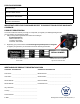
FOR YOUR RECORDS: Date of Purchase: Generator Model Number: Purchased from Store/Dealer: Generator Serial Number: IMPORTANT: KEEP YOUR PURCHASE RECEIPT TO ENSURE TROUBLE-FREE WARRANTY COVERAGE. PRODUCT REGISTRATION To ensure trouble-free warranty coverage, it is important you register your Westinghouse generator. You can register your generator by either: 1. Filling in the product registration form below and mailing to: Product Registration MWE Investments LLC 777 Manor Park Drive Columbus, Ohio 43228 2.
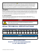
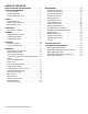
TABLE OF CONTENTS WGEN TECHNICAL SPECIFICATIONS. . . . . . . . . . . . . 2 PRODUCT REGISTRATION. . . . . . . . . . . . . . . . . . . . . . 3 For Your Records: . . . . . . . . . . . . . . . . . . . . . . . . . . . 3 Product Registration . . . . . . . . . . . . . . . . . . . . . . . . 3 Product Registration Form . . . . . . . . . . . . . . . . . . . . 3 SAFETY. . . . . . . . . . . . . . . . . . . . . . . . . . . . . . . . . . . . . . 5 Safety Definitions . . . . . . . . . . . . . . . . . . . . . . . . . . .
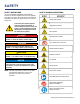
SAFETY SAFETY DEFINITIONS The words DANGER, WARNING, CAUTION and NOTICE are used throughout this manual to highlight important information. Be certain that the meanings of these alerts are known to all who work on or near the equipment. This safety alert symbol appears with most safety statements. It means attention, become alert, your safety is involved! Please read and abide by the message that follows the safety alerts symbol.
SAFETY GENERAL SAFETY RULES DANGER Never use the generator in a location that is wet or damp. Never expose the generator to rain, snow, water spray or standing water while in use. Protect the generator from all hazardous weather conditions. Moisture or ice can cause a short circuit or other malfunction in the electrical circuit. Never operate the generator in an enclosed area. Engine exhaust contains carbon monoxide. Only operate the generator outside and away from windows, doors and vents.
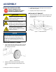
UNPACKING CAUTION Always have assistance when lifting the generator. The generator is heavy; lifting it could cause bodily harm. Avoid cutting on or near staples to prevent personal injury. WHAT COMES IN THE BOX (WGEN12000) Owners Manual Quick Start Guide/Maintenance Schedule Wireless Remote Starter (1) 1.
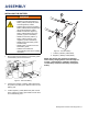
ASSEMBLY INSTALLING WHEELS AND FEET BEFORE ASSEMBLING THE GENERATOR, REVIEW THE SAFETY SECTION STARTING ON PAGE 5. CAUTION Never lift the generator without assistance. The generator is heavy and lifting without assistance could result in personal injury. 3. Install the hairpin cotter through the end of the axle bolt to lock it in place. 4. Repeat previous steps on other wheel. INSTALLING LIFT BRACKET 1.
ASSEMBLY 2 INSTALLING THE BATTERY WARNING To avoid electrics hock: • ALWAYS connect the positive (+) battery cable (red boot) first when connecting battery cables. • ALWAYS disconnect the negative (-) battery cable (black boot) first when disconnecting battery cables. • NEVER connect the negative (-) battery cable (black boot) to the positive (+) post on the battery. • NEVER connect the positive (+) battery cable (red boot) to the negative (-) post on the battery.
FEATURES 9 1 3 2 10 8 5 14 11 7 12 6 4 13 15 1 Push Button Electric Start: Starts and stops 12 Remote Start Pairing Button: Initiates the remote 2 Fuel Cap: Close until clicking sound is heard. 13 Alternator Cover: Gain access to alternator wiring. 3 Control Panel: Contains the circuit breakers 14 CARB Canister: Required for models sold into and 4 Battery: Included for electric start models. 15 Muffler and Spark Arrester: Avoid contact until the engine. and outlets.
FEATURES CONTROL PANEL FEATURES 10 120/240-Volt, 30-Amp Twist Lock Outlet 2 1 3 15 5 (NEMA L14-30R): Outlet can supply either 120V or 240V up to 30 amps. 6 11 120/240-Volt, 50-Amp Outlet (NEMA 14-50R): 4 12 8 7 9 ON OFF Outlet can supply either 120V or 240V up to 50 amps. 13 10 12 30-Amp Circuit Breaker: Circuit breaker limits the current that can be delivered through the 120volt duplex outlets to 30amps.
OPERATION BEFORE STARTING THE GENERATOR BEFORE STARTING THE GENERATOR, REVIEW SAFETY SECTION STARTING ON PAGE 5. Location Selection – Before starting the generator, avoid exhaust and location hazards by verifying: • You have selected a location to operate the generator that is outdoors and well ventilated. • You have selected a location with a level and solid surface on which to place the generator. • You have selected a location that is at least 15 feet (4.
OPERATION HIGH ALTITUDE OPERATION Engine power is reduced the higher you operate above sea level. Output will be reduced approximately 3.5% for every 1000ft of increased altitude from sea level. This is a natural occurrence and cannot be adjusted by engine. Increased exhaust emissions can also result due to increased fuel mixture. Other issues include hard starting, increased fuel consumption and spark plug fouling. Contact our service team 1-855-944-3571 for altitude part kits.
OPERATION POWER CORDS Using Extension Cords Westinghouse Portable Power assumes no responsibility for the content within this table. The use of this table is the responsibility of the user only. This table is intended for reference only. The results produced by using this table are not guaranteed to be correct or applicable in all situations as the type and construction of cords are highly variable.
OPERATION ADDING / CHECKING ENGINE FLUIDS AND FUEL BEFORE ADDING/CHECKING ENGINE FLUIDS AND FUEL, REVIEW SAFETY SECTION STARTING ON PAGE 5. ADDING GASOLINE TO THE FUEL TANK WARNING Never refuel the generator while the engine is running. DANGER Filling the fuel tank with gasoline while the generator is running can cause gasoline to leak and come in contact with hot surfaces that can ignite the gasoline.
OPERATION POWER OUTPUT AND DEMAND 120/240-Volt AC devices have two different electric power demands that must be taken into consideration, namely the running power and the starting/peak power. Both are measured in Watts (typically abbreviated as “W”). The steady state continuous load is the running power demand and this is often marked on the device near its model number or serial number. Sometimes the device might only be marked with its voltage (i.e. 120 V) and current draw (e.g.
OPERATION BEFORE STARTING THE GENERATOR BEFORE STARTING THE GENERATOR, REVIEW SAFETY SECTION STARTING ON PAGE 5. Before attempting to start the generator, verify the following: • The engine is filled with engine oil. See Checking Engine Oil. • The generator is situated in a proper location. See Location Selection. • The generator is on a dry surface. See Weather and Dry Surface. • All loads are disconnected from the generator. See No Connected Loads. • The generator is properly grounded the Generator.
OPERATION STARTING THE GENERATOR Be sure to check oil levels before starting. If it is the first time starting make sure to add oil (see Adding Engine Oil). 6. Push and hold the push button start for 1 second, then release. If using remote start then hold down START on the remote key fob until the generator starts, then release (see Figure 9). 1. Make sure nothing is plugged into power outlets. 2. Verify the battery is properly installed and both battery cables are attached (see Connecting the Battery).
OPERATION STOPPING THE GENERATOR Normal Operation During normal operation, use the following steps to stop your generator: 1. Remove any connected loads from the control panel receptacles. 2. Allow the generator to run at “no load” to reduce and stabilize engine and alternator temperatures. 3. Position the engine control switch to STOP (see figure 10). NOTE If you plan to store the generator after use, turn the fuel shutoff valve to the OFF position and allow the fuel to be consumed from the carburetor. 4.
MAINTENANCE MAINTENANCE SCHEDULE WARNING CAUTION Failure to perform periodic maintenance or not following maintenance procedures can cause the generator to malfunction and could result in death or serious injury. Avoid skin contact with engine oil or gasoline. Prolonged skin contact with engine oil or gasoline can be harmful. Frequent and prolonged contact with engine oil may cause skin cancer. Take protective measures and wear protective clothing and equipment.
MAINTENANCE ENGINE OIL MAINTENANCE Engine Oil Specification 1. Only use the engine oil specified in Figure 12. 2. Only use 4-stroke/cycle engine oil. NEVER USE 2-STROKE/CYCLE OIL. Synthetic oil is an acceptable substitute for conventional oil. 6. Check oil level: When checking the engine oil, remove the oil dipstick and wipe it clean. Push the oil dipstick all the way back in and then remove and check the oil level on the oil dipstick.
MAINTENANCE CHANGING ENGINE OIL 1. Stop the engine. 2. Let engine sit and cool for several minutes (allow crankcase pressure to equalize). 3. Place oil pan (or suitable container) under the oil drain plug (see Figure 16). 1. Turn off the generator and let it cool for several minutes if running. 2. Move the generator to a flat, level surface. 3. Locate the air filter cover on top of the engine. Unclip the 4 clips on the sides of the air filter cover (Figure 17). 4.
MAINTENANCE SPARK PLUG MAINTENANCE The spark plug must be checked and cleaned after every 100 hours of use or 6 months and must be replaced after 300 hours of use or every year. Recommended Spark Plug Replacement: NGK: (1034) BP7ES (Replacement) Bosch: F7TC (OE Spark Plug) Westinghouse Part Number: 180749 1. Stop the generator and let it cool for several minutes if running. 7. Install the spark plug by carefully following the steps outlined below: 2. Move the generator to a flat, level surface. 3.
MAINTENANCE CHECKING AND ADJUSTING VALVE LASH CAUTION Checking and adjusting valve lash must be done when the engine is cold. 1. Remove the rocker arm cover and carefully remove the gasket. If the gasket is torn or damaged, it must be replaced. 2. Remove the spark plug so the engine can be rotated more easily. 3. Rotate the engine to top dead center (TDC) of the compression stroke. Looking through the spark plug hole, the piston should be at the top. 4.
MAINTENANCE 8. Connect the black negative (-) battery cable to the battery second. 9. Install the battery hold-down plate using the nuts removed in step 2. 10. Install the spark plug wire onto spark plug. See below for the battery specification when replacing the battery. Model WGen12000 Westinghouse Part No.
TROUBLESHOOTING WARNING Before attempting to service or troubleshoot the generator, the owner or service technician must first read the owner’s manual and understand and follow all safety instructions. Failure to follow all instructions may result in conditions that can lead to voiding of the EPA certification or product warranty, serious personal injury, property damage or even death. PROBLEM POTENTIAL CAUSE SOLUTION 1. Circuit breakers are tripped. 1.
TROUBLESHOOTING PROBLEM Remote start system not working. Generator suddenly stops running. Engine runs erratic; does not hold a steady RPM. POTENTIAL CAUSE SOLUTION 1. Low battery in remote start key fob 1. Replace batteries in key fob. 2. Exceeding the range of remote start key fob 2. Move closer to generator. Must be no more than 100 ft away. 3. Remote start key fob not programmed to generator 3. Program key fob to generator. 1. Generator is out of fuel. 1. Check fuel level.
66 WGen12000 EXPLODED VIEW WESTINGHOUSE GENERATOR ACCESSORIES (CALL TO ORDER) 28 | Westinghouse Outdoor Power Equipment 210003 WGC25 25’ POWER CORD 210052 30A 6 BREAKER TRANSFER SWITCH KIT - MODEL WHMTS30 210075 25’ CORD 30AMP TRANSFER SWITCH 210076 50A 6 BREAKER TRANSFER SWITCH KIT - MODEL WHMTS50 130573 25’ L14-50R EXTENSION CORD (120/240-V, 50A OUTLET)
WGen12000 EXPLODED VIEW PART NO. NO. PART. DESCRIPTION NO. PART. DESCRIPTION 1 180784 ENGINE 38.5 130566 BATTERY CHARGING PORT 2.5MM 2 120560 FRONT COVER, ALTERNATOR 38.6 130569 DOUBLE USB SOCKET 3 120561 BOLT M10×1.25 38.7 130503 VFT METER 4 120562 ALTERNATOR ASSEMBLY 38.8 300673 THE CIRCUIT BREAKER 4.1 120526 GROUNDING POST COMP 38.9 130576 SWITCH 4.2 120525 CARBON BRUSH COMP 38.10 300674 GROUND BOLT ASSEMBLY 5 120563 WASHER,CRANKSHAFT 38.
WGen12000 ENGINE VIEW 30 | Westinghouse Outdoor Power Equipment
WGen12000 ENGINE VIEW PART NO. NO. PART. DESCRIPTION NO. PART.
WGen12000 ENGINE VIEW PART NO. NO. PART. DESCRIPTION NO. PART. DESCRIPTION 86 180740 BOLT M8X50 126 180779 LONG OIL TUBE 87 180741 STRAINER, OIL 127 180780 VALVE EXHAUST 88 180742 CRANKCASE DOWEL PIN 128 180775 PHILLIPS SCREW M8X50 89 180743 VALVE, IN 129 180774 SPACER, CARBURETOR 90 180744 LOCKING FLAPS 130 180773 CYLINDER HEAD, R 91 180745 CYLINDER HEAD GASKET 131 180772 SHROUD, R 92 180746 FLAT WASHER Φ10.
WGen12000 SCHEMATIC Westinghouse Outdoor Power Equipment | 33
Version 10.22.