
Installation Guide


4”&6” LED DOWNLIGHT INSTALLATION INSTRUCTIONS
Please read carefully and save these instructions, as you may
need them at a later date.
GENERAL: All electrical connections must be in accordance with local and
National Electrical Code (N.E.C.) standards. If you are unfamiliar with proper
electrical wiring connections obtain the services of a qualified electrician.
Remove the fixture from the box and make sure that no parts are missing. The
rubber behind the fixture will make the down light completely flush with ceiling all
the way around for better installation.
WARNING - Risk of fire or electric shock. LED Downlight installation requires
knowledge of luminaire electrical systems. If not qualified, do not attempt
installation. Contact a qualified electrician.
Do not make or alter any open holes in an enclosure of wiring or electrical
components during kit installation.
WARNING - To prevent wiring damage or abrasion, do not expose wiring to
edges of sheet metal or other sharp objects.
THIS PRODUCT MUST BE INSTALLED IN ACCORDANCE WITH THE
APPLICABLE INSTALLATION CODE BY A PERSON FAMILIAR WITH THE
CONSTRUCTION AND OPERATION OF THE PRODUCT AND THE HAZARDS
INVOLVED
ASSEMBLY AND INSTALLATION
1. Turn off power at circuit box to avoid possible electric shock.
2. Themal radiation space and irradiation distance must be ensured. The height of the
fixture should be no less than 3- 15/16" (100mm) (Figure 1).
3. Locate a suitable position to place the downlight and cut a hole in accordance to the
cut-hole diameters as shown (Figure 1).
4" retrofit: 4- 3/8" - 4- 3/4" (110mm - 120mm) /
6" retrofit: 5- 1/2" - 6- 1/4" (140mm - 160mm)
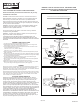
4. Slide the electrical compartment door (A) up to access the downlight's black (line) and
white (neutral) wires.
5. Remove knock-out(s) (B) carefully with a screw driver, install strain reliefs (not included)
into the konck-out(s) and insert electrical wires from electrical box through strain relief(s)
into downlight's electrical compartment.
6. Connect (push) electrical wires from electric box into the correct inserts using the
provided connectors (C). Black (Line) - White (Neutral).
7. Place wires back into the driver housing (D) and snap back the electrical compartment
door into place.
8. Slide torsion spring covers (E) onto the ends of the torsion springs (F).
9. Bend back the two torion springs and fit the fixture in the hole in ceiling. Slowy release
unit up to the ceiling and the springs will hold fixture in place (Figure 3).
DIMMING
Although this product is compatible with most common residential type dimmers, dimming
performance depends on dimmer, dimmer setting (for dimmers with brightness range
adjustments), wiring method, and the number of LED modules. For best results, set dimmer
position at maximum before adjusting to a lower light level.
Recommended Dimmers (minimum load for four LED modules maybe required for optimal
dimming performance): Lutron DVCL-153P, Lutron AYCL-153P, Lutron LECL-153P, Lutron
CTCL-153P, Lutron TGCL-153P, Lutron SCL-153P, Lutron DV-600P, Lutron DV-603P,
Lutron AY-603P, Lutron S-603P, Leviton 6672
FIVE-YEAR LIMITED WARRANTY
Westinghouse Lighting warrants that this lamp will be free from defects in
material and workmanship and will work for 5 years (based on up to 3 hours
average usage per day for 7 days per week). If the product fails during the
warranty period, return defective product to retailer. Warranty terms and
conditions of retailer apply. If replacement product is not available at retail store,
please contact consumersupport@westinghouselighting.com or return the
product in the original package with receipt to manufacturer at: 12401 McNulty
Road, Philadelphia, PA 19154-1029. This limited warranty does not cover lamps
subject to accident, neglect, abuse, misuse or acts of God. REPLACEMENT IS
YOUR SOLE REMEDY. EXCEPT TO THE EXTENT PROHIBITED BY
APPLICABLE LAW, ANY IMPLIED WARRANTIES ARE LIMITED TO THE
DURATION OF THIS WARRANTY PERIOD. LIABILITY FOR INCIDENTAL OR
CONSEQUENTIAL DAMAGES IS EXPRESSLY EXCLUDED. Some states do
not allow exclusion of incidental or consequential damages, so the above
exclusion may not apply. This warranty gives you specific legal rights, but you
may also have other rights that vary from state to state.
WARNING - RISK OF ELECTRIC SHOCK. DISCONNECT MAIN
POWER AT FUSE OR CIRCUIT BREAKER BEFORE INSTALLING
OR SERVICING THE FIXTURE.
FIG. 2
FIG. 3
FIG. 1
4- 3/8" - 4- 3/4"
(110 - 120mm)
3- 15/16" (100mm)
4 in.
5- 1/2" - 6- 1/4"
(140 - 160mm)
6 in.
ES-WH-040
Made in China
®
Electrical
Compartment
Door (A)
Torsion
Spring(s) (F)
Driver
Housing (D)
Torsion Spring
Cover(s) (E)
Knock-outs(s) (B)
Strain Relief
(not included)
Connectors (C)