
Instructions / Assembly


3” & 4” LED DOWNLIGHT INSTALLATION INSTRUCTIONS
Please read carefully and save these instructions, as you may
need them at a later date.
GENERAL: All electrical connections must be in accordance with local and
National Electrical Code (N.E.C.) standards. If you are unfamiliar with proper
electrical wiring connections obtain the services of a qualified electrician.
Remove the fixture from the box and make sure that no parts are missing. The
rubber behind the fixture will make the down light completely flush with ceiling all
the way around for better installation.
WARNING - Risk of fire or electric shock. LED Downlight installation requires
knowledge of luminaire electrical systems. If not qualified, do not attempt
installation. Contact a qualified electrician.
Do not make or alter any open holes in an enclosure of wiring or electrical
components during kit installation.
WARNING - To prevent wiring damage or abrasion, do not expose wiring to
edges of sheet metal or other sharp objects.
SUITABLE FOR OPERATION IN AMBIENT NOT EXCEEDING 45°C
MIN 90°C SUPPLY CONDUCTORS.
THIS PRODUCT MUST BE INSTALLED IN ACCORDANCE WITH THE
APPLICABLE INSTALLATION CODE BY A PERSON FAMILIAR WITH THE
CONSTRUCTION AND OPERATION OF THE PRODUCT AND THE HAZARDS
INVOLVED.
ASSEMBLY AND INSTALLATION
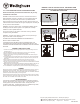
1. Cut hole in the ceiling for the downlight as planned according to the design and local
regulations (Fig. 2).
2. Run the electrical wire from the switch through the mounting hole in the ceiling.
3. Open the junction box and remove the appropriate knockouts.
4. Insert the power supply wire through the knockout and fasten with a strain relief (not
included) (Fig. 3).
5. Connect the ground wire to yellow-green wire in the junction box. Connect power leads
in ceiling to the black and white wires in junction box (black on black etc). Secure with
strain relief.
6. Put all wires and connections back into the box and close the cover securely.
7. Insert junction box through the mounting hole and secure to ceiling joist (Fig. 4).
8. Plug the connector from the fixture into the connector from the electrical box and twist as
shown in Figure 4 to secure in place.
9.
Bend back the two torsion springs and fit the fixture in the hole (or square) in ceiling (Fig. 5).
Slowly release unit up to the ceiling and the springs will hold fixture in place (Fig. 6).
10. Once installation is complete, switch on power to confirm the lamp is working properly.
DIMMING
Although this product is compatible with most common residential type dimmers, dimming
performance depends on dimmer, dimmer setting (for dimmers with brightness range
adjustments), wiring method, and the number of LED modules. For best results, set dimmer
position at maximum before adjusting to a lower light level.
Recommended Dimmers (minimum load for four LED modules maybe required for optimal
dimming performance): Lutron DVCL-153P, Lutron CTCL-153P, Lutron TGCL-153P, Lutron
SCL-153P, Lutron DV-600P, Lutron S-600P, Leviton 6672
LIMITED WARRANTY
This lumaniare is warranted to be free from defects in materials and workman-
ship for 5 years (based on using 3 hours per day). If the product fails during the
warranty period, return defective product to seller. Warranty terms and
conditions of seller apply. If replacement product is not available through seller,
please contact www.westinghouselighting.com/contact-us.
WARNING - RISK OF ELECTRIC SHOCK. DISCONNECT MAIN
POWER AT FUSE OR CIRCUIT BREAKER BEFORE INSTALLING
OR SERVICING THE FIXTURE.
ESF-WH-068
Westinghouse Lighting, Philadelphia, PA 19154-1029, U.S.A. www.westinghouselighting.com
, WESTINGHOUSE, and INNOVATION YOU CAN BE SURE OF are trademarks of Westinghouse Electric Corporation.
Used under license by Westinghouse Lighting All rights reserved. Made in China
3" Gimbal Downlight
: Ø70mm
4" Gimbal Downlight : Ø108mm
FIG. 1 FIG. 2
FIG. 3 FIG. 4
FIG. 5
FIG. 6
L - Black wire
N - White wire
- Yellow/green
wire
Strain
relief