
Installation Sheet


WARNINGS:
•
To avoid fire, shock, and serious personal injury, follow all
instructions carefully. Read and save these instructions for
future reference.
•
Do not install or use this unit if any part is damaged or miss-
ing.
•
IMPORTANT!
Fan installation must be complete, including the
assembly of blades, before testing the remote control unit.
NOTICE:
SAFETY PRECAUTIONS:
1.
This remote control is rated for a maximum of 1.2 Motor amp at 120 volts,
and total bulb wattage equaling 100 Watt maximum.
2. Do
not
use
with
DC solid state ceiling fans.
3. The
decorative
housing
(canopy)
at
the
ceiling
must
be
metal.
The
metal
housing
acts
as
a
protective
cover
for
the
Control
Unit.
DO NOT USE WITH A
NON-METALLIC HOUSING.
4. Only the remote unit should be used to change fan speeds. Do not use
the
pull
chain
to change
fan
speeds
after
installation.
5. Make
sure
no bare
wires
are
exposed
outside
of
the
connectors.
6. All wiring must conform to national and local electrical codes. If you
feel that you do not have enough electrical wiring knowledge or experi-
ence, have your fan control installed by a qualified licensed electrician.
Any electrical work not described in this manual should be
performedby a qualified licensed electrician.
7. Do not use water or detergents to clean the remote transmitter unit. A
dry dust cloth will be suitable for most cleaning.
8. Use of this control with some ceiling fans could result in fire, shock,
and serious personal injury. Use this fan control only with capacitor
speed controlled ceiling fans only.
WARNING: HIGH VOLTAGE
Before connecting this control unit:
• Disconnect electrical power from the circuit to be used.
• Household power can cause serious injury or death.
• Wiring must meet all local electrical code requirements.
A. MAKING THE ELECTRICAL CONNECTIONS:
NOTE: This remote only works
with some fans when mounted on
sloped ceilings.
Do not use fan speed control in
canopies where the mounting is
not as described in figures 4 or 5.
This remote cannot be installed in a
downrod style fan when installed as
flushmount (when downrod is not in use).
1. Disconnect existing wiring between ceiling fan and AC sup-
ply at electrical junction box.
2.
FOR FANS ON A DOWNROD:
Remove ceiling fan canopy
from its mounting plate.
FOR FLUSHMOUNT FANS:
Remove decorative housing
from mounting plate (see figure 2). Disconnect mounting
bracket from mounting plate and allow to hang from one side
(see figure 3).
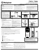
3. Making the electrical connection (see Figure 1):
• Connect GREEN fan wire to BARE (ground) wire.
• Connect BLACK receiver unit wire to BLACK supply wire
(AC LINE).
• Connect WHITE receiver unit wire to WHITE supply wire
(AC NEUTRAL).
• Connect WHITE receiver unit wire (MOTOR N) to WHITE
fan wire.
• Push the connected wires up into the junction box.
Place
BLACK wires on one side of box, and WHITE, GREEN
and
BARE (ground) wires on the other side of the box.
•
Connect
BLACK receiver unit wire (MOTOR L) to BLACK fan wire.
• Connect BLUE receiver unit wire (FOR LIGHT) to BLUE
light wire.
• Push the connected wires up into the junction box.
• Lay the BLACK control unit wire (ANTENNA) on top of the
control unit.
•
FOR FANS ON A DOWNROD:
Lay the control unit in the
canopy (see figure 4). Reinstall the canopy on its mount-
ing plate. Restore electrical power to the circuit.
• FOR FLUSHMOUNT FANS:
Attach the control unit to
the mounting plate or to the ceiling with the supplied tie
wraps (see figure 5). Reconnect the mounting bracket to
the mounting plate (see figure 2). Reinstall the decorative
housing on its mounting plate. Restore electrical power to
the circuit.
NOTE: If the unit does not fit properly between the
mounting plate and ceiling, attach the unit to the
underside of the mounting plate.
BLACK BLACK
WHITE WHITE
BLUE
BLACK BLACK
WHITE WHITE
BLUE
RECEIVER
UNIT
LIGHT
FAN
FAN
AC LINE
AC NEUTRAL
BARE (GROUND) GREEN FAN
AC SUPPLY
FIGURE 1
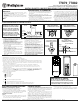
FIGURE - 2
FLUSHMOUNT FANS ONLY
FIGURE - 3
FLUSHMOUNT FANS ONLY
RECEIVER
UNIT
FIGURE - 4
DOWNROD FANS ONLY
CEILING
JUNCTION BOX
MOUNTING PLATE
RECEIVER UNIT
FIGURE - 5
FLUSHMOUNT FANS ONLY
TROUBLESHOOTING GUIDE
PROBLEM: REMOTE FAILS TO OPERATE
Check:
• Is there power to the receiver unit?
• Is the receiver unit wired correctly?
• Are the fan and light switches set on the highest position?
• Is there a good battery in the remote? If the red indicator lights when either
button is pushed, the battery is good.
PROBLEM: SHORT RANGE
Solution:
•
If the remote can operate the receiver unit when close to it but does not oper-
ate it at distances of 30-50 feet, try placing the black antenna wire above the
ceiling and outside of the junction box.
LIMITED WARRANTY
The Westinghouse remote control for ceiling fans offers a limited war-
ranty of one year from the date of purchase to the original owner against
defects in material and workmanship. All spare parts are covered for
ninety days only. This warranty is in lieu of all other warranties expressed or
implied.
Westinghouse will repair or replace this remote control if it is defec-
tive due to faulty materials or workmanship. This warranty does not cover
ser
vice charges, batteries, defects resulting from accidents, damages caused
through abuse or alterations or by affixing any attachment not provided with
the product, improper installation or maintenance, failure of supporting
devices not supplied as original mounting hardware, exposures to extremes
of heat or humidity, incorrect voltage, surges in current,
unauthorized repair, or failures caused by modifications of the product or the
acts of third parties. See remote manual for proper installation.
If this product fails for any reason covered by this warranty,
please contact us at www.westinghouselighting.com/contact-us.
B. SETTING THE OPERATING CONTROLS (FIRST TIME ONLY):
1. This unit operates on two 1.5V AAA batteries (included).
2.
Store the controller unit away from excess heat or humidity.
3.
The remote control adopts RF wireless digit emission technique.
4.
The transmitter and receiver are matched at the factory. Please follow the next step to reprogram when the pairing is failed.
5.
Turn off the fan power and then restore it, press and hold the "fan stop" button for 5 seconds,within 60 seconds after you
restore the power, the fan will automatic turn on at low speed
and then turn off, with the light flashing 3 times.
(NOTE: The pairing process is not accepted after 60 seconds when you restore supply power)
6.
Please note the transmitter can pair with multiple receivers. When the transmitter does not control the receiver,
please check if any similar remote controls are working nearby, disconnect them and then proceed with pairing
process again.
7.
If your ceiling fan is equipped with variable speed and light ON/OFF pull chain switch control, make sure to set the
speed control at the HIGHEST speed and the light to the ON or BRIGHTEST position before installing the
remote control. This will avoid erratic speeds
and possible damage to your ceiling fan.
77879_77882
Installation & Operating Instructions for the
Westinghouse Ceiling Fan and Light Remote Control
WARNING: SHUT POWER OFF AT FUSE OR CIRCUIT BREAKER
Westinghouse Lighting, Philadelphia, PA 19154-1029, U.S.A. www.westinghouselighting , WESTINGHOUSE, and INNOVATION YOU CAN BE SURE OF are trademarks of Westinghouse Electric Corporation. Used under license by Westinghouse Lighting. All rights reserved. Made in China
8 . Operation buttons on the panel of the transmitter:
(1) Fan speed:
= High speed
= Medium-high speed
= Medium speed
= Low speed
(2) - On/Off Button: Turn the fan off
(3)
- Light On/Off – press and release light button.
- Light Dimmer - continuously press the light button to brighten the light
- Light Dimmer - continuously press the light button to dim the light.
ANTENNA