
Owner's Manual

21
OPERATION
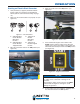
Using Westinghouse Power Cord
Use the extension cord chart to determine the size
of the conductor for extension cord applications.
Determine the distance of the generator to the
appliance on the top line of the chart. Then select the
rated amperage of the generator on the left side of the
chart. Where the two meet is the size of the conductor
required for the application.
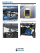
The WCG25 power cord is connected to the generator
at the 120/240 plug. The opposite end of the power
cord is a fan tail receptacle with 2 green receptacles
and 2 red receptacles. Each receptacle is rated at
120 volts AC. To balance the load on the generator’s
alternator, use the red and green identifiers on the fan
tail receptacle. To keep the load balanced, connect
the loads so that both color receptacles are used. An
example is one in red and one in green. Do not connect
2 in red and none in green, or 2 in green and none in
red. If only one color receptacle is used with multiple
loads, the alternator may experience an unbalanced
load, causing undue vibration to generator.
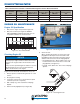
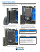
1
2
Figure 13
1 - Green Dots 2 - Red Dots
TRANSFER SWITCH
CONNECTIONS
The Westinghouse generator is wired with the neutral
bonded to ground. If you are connecting your generator
to a transfer switch, the electrician must first determine
what type transfer switch is being used. Transfer
switches for this equipment are either two-pole or three-
pole types.
A two-pole transfer switch will not switch the neutral
from the generator to the service panel. That means
the generator will be grounded to the service panel. To
use the generator with two-pole transfer switches, the
electrician will need to change the neutral from bonded
to floating.
This is done by removing the jumper wire that connects
the alternator ground to the alternator neutral. Remove
the jumper wire and retighten the connections. Keep
the jumper wire with the owner’s manual in case it is
needed for future use when not connected to a transfer
switch.
Figure 14