California Proposition 65 Warning California Proposition 65 Warning The engine exhaust from this product contains chemicals known to the state of California to cause cancer, birth defects or other reproductive harm. Certain components in this product and its related accessories contain chemicals known to the state of California to cause cancer, birth defects or other reproductive harm. Wash hands after handling.
CONGRATULATIONS ON OWNING A WESTINGHOUSE GENERATOR ! DANGER This manual contains important instructions for operating this generator. For your safety and the safety of others, be sure to read this manual thoroughly before operating the generator. Failure to properly follow all instructions and precautions can cause you and others to be seriously hurt or killed.
MODEL NUMBER REFERENCE EPA (49 States) WH3250 WH4500 WH5500 WH6000 WH6000S WH6500E WH7000 WH7000E WH7500E EPA (49 States) and CARB (50 States) WH3250 WH5500 WH7000E WH7500E CSA (Canada) WHC6500 WHC6000S WHC6500E WHC7000EGC Suffix: E – Electric Start S – Storm Unit C – CARB Unit GC – Generator Cord Prefix: WHC – CSA Certified 4
TABLE OF CONTENTS CONGRATULATIONS ON OWNING A WESTINGHOUSE GENERATOR..........................................................3 For Your Records:..........................................................................................................................................3 Product Registration......................................................................................................................................3 Product Registration Form..............................................
TABLE OF CONTENTS PRODUCT WARRANTY APPLICATIONS AND PRODUCT WARRANTY PERIODS.................................39 CONSUMER APPLICATION.................................................................................................................39 COMMERCIAL APPLICATION.............................................................................................................39 NON-WARRANTABLE APPLICATIONS...............................................................................................
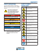
SAFETY SAFETY DEFINITIONS The words DANGER, WARNING, CAUTION and NOTICE are used throughout this manual to highlight important information. Be certain that the meanings of these alerts are known to all who work on or near the equipment. ! This safety alert symbol appears with most safety statements. It means attention, become alert, your safety is involved! Please read and abide by the message that follows the safety alert symbol.
SAFETY GENERAL SAFETY RULES ! DANGER Never use the generator in a location that is wet or damp. Never expose the generator to rain, snow, water spray or standing water while in use. Protect the generator from all hazardous weather conditions. Moisture or ice can cause a short circuit or other malfunction in the electrical circuit. Never operate the generator in an enclosed area. Engine exhaust contains carbon monoxide. Only operate the generator outside and away from windows, doors and vents.
SAFETY ! WARNING Never operate the generator if powered items overheat, electrical output drops, there is sparking, flames or smoke coming from the generator, or if the receptacles are damaged. ! Never use the generator to power medical support equipment. Always remove any tools or other service equipment used during maintenance from the generator before operating. NOTICE Never modify the generator.
SAFETY SAFETY LABELS AND DECALS 2 3 4 1 5 2 1 3 5 4 Figure 1 10
SAFETY 2 5 3 1 4 1 2 3 5 4 Figure 2 11
UNPACKING UNPACKING THE GENERATOR 1 3 ! CAUTION Always have assistance when lifting the generator. The generator is heavy; lifting it could cause bodily harm. ! 2 Avoid cutting on or near staples to prevent personal injury. Tools required – box cutter or similar device. 1. Carefully cut the packing tape on top of the carton. 4 2. Fold back top flaps to reveal the manual. 3. Remove the Wheel Kit Accessories cardboard box. 4. Carefully cut two sides of the carton to remove the generator.
ASSEMBLY ASSEMBLY 1. Place generator on a flat surface. Before assembling the generator, review Safety on page 7 and the following safety messages. 2. Place a piece of cardboard or other soft material to tip the generator onto, to protect the frame paint and prevent the generator from sliding. Tip the generator onto its side as shown in Figure 4 (engine should be on the bottom). ! CAUTION Never lift the generator without assistance.
ASSEMBLY 3. Install the mounting foot to the frame using M8 flange bolts and nuts. 3 2 3 6. Install the handles using the clevis pin and hairpin cotter as shown in Figure 7. 1 3 1 2 4 Figure 5 – Assemble Mounting Foot to Frame 1 - Rubber Pads 2 - Mounting Foot 3 - M8 Flange Bolt and Nut 4. Install the 16 mm x 105 mm axle pin through the axle bracket on the frame. 5. Install the hairpin cotter through the axle pin.
ASSEMBLY INSTALLING THE BATTERY (ELECTRIC START GENERATORS ONLY) 2 ! WARNING To avoid electric shock: • ALWAYS connect the positive (+) battery cable (red boot) first when connecting battery cables. • ALWAYS disconnect the negative (-) battery cable (black boot) first when disconnecting battery cables. • NEVER connect the negative (-) battery cable (black boot) to the positive (+) post on the battery. • NEVER connect the positive (+) battery cable (red boot) to the negative (-) post on the battery.
FEATURES GENERAL GENERATOR FEATURES 2 3 1 4 7 6 5 Figure 9 1- E ngine Control Switch: Turns the engine on and off. 2 - Fuel Cap: Close until clicking sound is heard. 6- O il Fill Plug/Dipstick: Must be removed to add and check oil. 3- C ontrol Panel: Contains the circuit breakers and outlets. 7- O il Drain Plug: Must be removed to drain engine oil. 4- M uffler and Spark Arrester: Avoid contact until engine is cooled down. Spark arrestor prevents sparks from exiting the muffler.
FEATURES 1 2 3 5 4 7 6 Figure 10 1 - Fuel Gauge: Indicates fuel level. 2- F uel Shutoff Valve: Controls the flow of fuel to the engine. 3- R ecoil Handle: Must pull to start engine for manual start units. 4- A ir Cleaner Cover: Must remove to service the air cleaner. 5- C hoke Lever: Must be put in the ON position to start the engine and returned to the OFF position once the engine is running. 6- C ARB Canister: Model numbers followed by a “C” will be equipped with a carbon canister.
FEATURES CONTROL PANEL FEATURES 1 2 3 5 4 6 8 7 Figure 11 – Control Panel Features 1. Engine Control Switch (RUN/STOP for Manual Start Units): • RUN - In the RUN position, the switch allows the generator to be started (for manual start models). • STOP - In the STOP position, the switch stops the engine. 2. Hour Meter: Displays how many hours the generator has been run when under load. 3. Main Circuit Breaker: The main circuit breaker controls total output of all outlets to protect the generator. 4.
OPERATION BEFORE STARTING THE GENERATOR Before starting the generator, review Safety on page 7. Location Selection – Before starting the generator, avoid exhaust and location hazards by verifying: • You have selected a location to operate the generator that is outdoors and well ventilated. • You have selected a location with a level and solid surface on which to place the generator. • You have selected a location that is at least 6 feet (1.
OPERATION ! WARNING Be sure the generator is properly connected to earth ground before operating. The generator must be grounded to prevent electrical shock due to faulty appliances. POWER CORD Using Extension Cords Westpro Power Systems assumes no responsibility for the content within this table. The use of this table is the responsibility of the user only. This table is intended for reference only.
OPERATION Using Westinghouse Power Cord Use the extension cord chart to determine the size of the conductor for extension cord applications. Determine the distance of the generator to the appliance on the top line of the chart. Then select the rated amperage of the generator on the left side of the chart. Where the two meet is the size of the conductor required for the application. The WCG25 power cord is connected to the generator at the 120/240 plug.
OPERATION ADDING / CHECKING ENGINE FLUIDS AND FUEL Adding Gasoline to the Fuel Tank ! WARNING Never refuel the generator while the engine is running. Before adding/checking engine fluids and fuel, review Safety on page 7. Always turn the engine off and allow the generator to cool before refueling. ! DANGER Filling the fuel tank with gasoline while the generator is running can cause gasoline to leak and come in contact with hot surfaces that can ignite the gasoline.
OPERATION STARTING THE GENERATOR Before starting the generator, review Safety on page 7. Before attempting to start the generator, verify the following: • The engine is filled with engine oil (see Checking Engine Oil on page 28). • The generator is situated in a proper location (see Location Selection on page 19). NOTICE The engine is equipped with a low oil shutdown switch. If the oil level becomes low, the engine will shut down and will not start until the oil is filled to the proper level.
OPERATION 2. Move the fuel shutoff valve to the ON position (see Figure 17). 4. Push the engine control switch into the RUN position (see Figure 19). Figure 19 – Engine Control Switch Figure 17 – Fuel Shutoff Valve in the ON Position 3. Move the choke lever to the ON position (see Figure 18). Figure 18 – Choke Lever 5. Firmly grasp and pull the recoil handle slowly until you feel increased resistance.
OPERATION Starting an Electric Start Generator 1. Verify the battery is properly installed and both battery cables are attached (see Installing the Battery (Electric Start Generators Only) on page 15). 4. Move the choke lever to the ON position (see Figure 23). 2. Make sure the circuit breakers are properly set (see Figure 21).
OPERATION NNOTE: If the engine fails to start after 5 seconds, release the engine control switch. Let the generator sit idle for 15 seconds and then repeat step 5. If the cranking speed drops after each unsuccessful attempt, then the battery may not be adequately charged. Manually start the generator as instructed in Manually Starting a Generator on page 23. NNOTE: The electric start generator is equipped with a battery charging feature.
MAINTENANCE MAINTENANCE ! CAUTION Before performing maintenance on the generator, review Safety on page 7 and the following safety messages. Avoid skin contact with engine oil or gasoline. Prolonged skin contact with engine oil or gasoline can be harmful. Frequent and prolonged contact with engine oil may cause skin cancer. Take protective measures and wear protective clothing and equipment. Wash all exposed skin with soap and water.
MAINTENANCE Table 2: Maintenance Schedule - Authorized Westinghouse Service Dealer Performed Maintenance Item Before Every Use After First 20 Hours or First Month of Use After 50 Hours of Use or Every 3 Months After 100 Hours of Use or Every 6 Months After 300 Hours of Use or Every Year Valve Clearance – – – – Check/Adjust Fuel Filter – – – Check/Clean – Idle Speed – – – – Check/Adjust ENGINE OIL MAINTENANCE Engine Oil Specification 1. Only use the engine oil specified in Figure 25.
MAINTENANCE Adding Engine Oil 1. Always operate or maintain the generator on a flat surface. 5. Remove the oil drain plug (see Figure 29). Once removed, place the oil drain plug on a clean surface. 2. Stop engine if running. 3. Let engine sit and cool for several minutes (allow crankcase pressure to equalize). 4. Thoroughly clean around the oil fill plug/dipstick. 5. Remove oil fill plug/dipstick and wipe clean. 6. Select the proper engine oil as specified in Figure 23. 7.
MAINTENANCE 2. Move the generator to a flat, level surface. 3. Unclip the clips on the top and bottom of the air filter cover (see Figure 30) and remove the air filter cover. Figure 30 – Removing Air Filter Cover 4. Remove the black coarse outside air filter (see Figure 31). 5. Remove the gray fine inside air filter (see Figure 32). Figure 32 – Removing Fine Inside Air Filter 6. Wash the foam air filter elements by submerging the elements in a solution of household detergent soap and warm water.
MAINTENANCE 9. Dry the air filter elements by again applying a slow firm squeezing action. 10. Once the air filters are dry, coat the air filters with clean engine oil (see Figure 33). 14. Install the air filter cover by clipping the clips on the top and bottom of the air filter assembly (see Figure 35). Figure 33 11. Squeeze the filters to remove any excess oil (see Figure 34). Figure 35 – Installation of Air Filter Cover Figure 34 12.
MAINTENANCE SPARK PLUG MAINTENANCE The spark plug must be checked and cleaned after every 100 hours of use or 6 months and must be replaced after 300 hours of use or every year. 1. Stop the generator and let it cool for several minutes if running. 2. Move the generator to a flat, level surface. 3. Remove the spark plug boot by firmly pulling the plastic spark plug boot handle directly away from the engine (see Figure 36).
MAINTENANCE 8. Install the spark plug by carefully following the steps outlined below: a - Carefully insert the spark plug back into the cylinder head. Hand-thread the spark plug until it bottoms out. 2. Loosen and remove the nuts on the battery holddown plate and remove the plate from the support rods (see Figure 39). 1 2 b - Using the 13/16" spark plug socket wrench provided, turn the spark plug to ensure it is fully seated.
MAINTENANCE CLEANING THE SPARK ARRESTOR 2 Check and clean the spark arrestor after every 100 hours of use or 6 months. 1. Stop the generator and let it cool for several minutes if running. 2. Move the generator to a flat, level surface. 3. Using a flathead screwdriver, loosen the spark arrestor band clamp (see Figure 41).
MAINTENANCE CLEANING THE GENERATOR It is important to inspect and clean the generator before every use. Clean All Engine Air Inlet and Outlet Ports – Make sure all engine air inlet and outlet ports are clean of any dirt and debris to ensure the engine does not run hot (see Figure 42). Clean All Alternator Cooling Air Inlets and Exhaust Ports – Make sure the cooling air inlets and exhaust ports of the alternator are free of any debris and obstructions.
MAINTENANCE STORAGE ! WARNING Never store a generator with fuel in the tank indoors or in a poorly ventilated area where the fumes can come in contact with an ignition source such as a: 1) pilot light of a stove, water heater, clothes dryer or any other gas appliance; or 2) spark from an electric appliance. NOTICE Gasoline stored for as little as 60 days can go bad, causing gum, varnish and corrosive buildup in fuel lines, fuel passages and the engine.
TROUBLESHOOTING TROUBLESHOOTING ! WARNING Before attempting to service or troubleshoot the generator, the owner or service technician must first read the owner’s manual and understand and follow all safety instructions. Failure to follow all instructions may result in conditions that can lead to voiding of the EPA certification or product warranty, serious personal injury, property damage or even death. PROBLEM Engine is running, but no electrical output.
TROUBLESHOOTING PROBLEM Generator suddenly stops running. Engine runs erratic; does not hold a steady RPM. 38 POTENTIAL CAUSE SOLUTION 1. Generator is out of fuel. 1. Check fuel level (see page 22). Add fuel if necessary. 2. The low oil shutdown switch has stopped the engine. 2. Check oil level and add oil if necessary (see pages 28 and 22. 3. Too much load 3. Restart the generator and reduce the load. 4.
WARRANTY WESTPRO POWER SYSTEMS “THREE YEAR” LIMITED WARRANTY Effective July 1, 2011 WESTPRO’S RESPONSIBILITY Westpro Power Systems, LLC (“WESTPRO”) warrants to the original purchaser that its Westinghouse line of generators will be free from defects in material and workmanship.
WARRANTY NON-WARRANTABLE APPLICATIONS THE WESTPRO WESTINGHOUSE LINE OF GENERATORS IS EXPRESSLY NOT RECOMMENDED FOR NOR WARRANTED FOR THE FOLLOWING APPLICATIONS: Medical and Life Support Uses – This product is not recommended for and is NOT warranted for the use to power Medical and Life Support equipment or devices.
MANUAL DEL PROPIETARIO
California Proposition 65 Warning California Proposition 65 Warning The engine exhaust from this product contains chemicals known to the state of California to cause cancer, birth defects or other reproductive harm. Certain components in this product and its related accessories contain chemicals known to the state of California to cause cancer, birth defects or other reproductive harm. Wash hands after handling.
FELICITACIONES POR ADQUIRIR UN GENERADOR WESTINGHOUSE ! PELIGRO Este manual contine instrucciones importantes para la operación de este generador. Para su seguridad y la de los demás, debe leer este manual completamente antes de operar el generador. Si no sigue adecuadamente todas las instrucciones y precauciones, usted y otras personas pueden resultar gravemente heridos o morir.
NÚMERO DE MODELO REFERENCIA EPA (49 Estados) WH3250 WH4500 WH5500 WH6000 WH6000S WH6500E WH7000 WH7000E WH7500E EPA (49 Estados) and CARB (50 Estados) WH3250 WH5500 WH7000E WH7500E CSA (Canada) WHC6500 WHC6000S WHC6500E WHC7000EGC Sufijo: E – Arranque Eléctrico S – Unidad Tormenta C – Unidad CARB GC – Cable Generador Prefijo: WHC – CSA Certificado 4
ÍNDICE FELICITACIONES POR ADQUIRIR UN GENERADOR WESTINGHOUSE .......................................................3 Para sus registros: ........................................................................................................................................3 Registro del producto:...................................................................................................................................3 Formulario de registro del producto..............................................
ÍNDICE APLICACIONES Y PERÍODOS DE LA GARANTÍA DEL PRODUCTO ......................................................41 APLICACIÓN PARA EL CONSUMO ....................................................................................................41 APLICACIÓN COMERCIAL .................................................................................................................42 APLICACIONES NO GARANTIZABLES .............................................................................................
SEGURIDAD DEFINICIONES DE SEGURIDAD Las palabras PELIGRO, ADVERTENCIA, PRECAUCIÓN y AVISO se usan a lo largo de este manual para destacar la información importante. Asegúrese de que todo aquel que trabaje con el equipo o cerca de él conozca el significado de estas alertas. ! Este símbolo de alerta de seguridad aparece con la mayoría de las declaraciones de seguridad.
SEGURIDAD NORMAS GENERALES DE SEGURIDAD ! PELIGRO Nunca use el generador en lugares mojados o húmedos. Nunca exponga el generador a lluvia, nieve, rociado de agua o agua estancada durante el uso. Proteja el generador de todas las condiciones climáticas peligrosas. La humedad o el hielo pueden causar un cortocircuito u otro tipo de problema de funcionamiento en el circuito eléctrico. Nunca opere el generador en un lugar cerrado. El escape del motor contiene monóxido de carbono.
SEGURIDAD ! ADVERTENCIA Nunca opere el generador si se sobrecalientan los componentes eléctricos, si cae la salida de energía eléctrica, si salen chispas, llamas o humo del generador, o si los receptáculos están calientes. ! Nunca use el generador para alimentar equipos de asistencia médica. Siempre retire del generador las herramientas u otros equipos de servicio que se utilicen durante el mantenimiento antes de usarlo. AVISO Nunca modifique el generador.
SEGURIDAD ETIQUETAS Y CALCOMANÍAS DE SEGURIDAD 2 3 4 1 5 2 1 3 5 4 Figura 1 10
SEGURIDAD 2 5 3 1 4 1 2 3 5 4 Figura 2 11
DESEMBALAR PROCEDIMIENTO PARA DESEMBALAR EL GENERADOR 1 3 ! PRECAUCIÓN 2 Siempre debe solicitar ayuda para levantar el generador. El generador es pesado, levantarlo puede causarle lesiones físicas. ! Evite cortar sobre o cerca de grapas para evitar lesiones personales. 4 Herramientas requeridas: trincheta o dispositivo similar. 1. Corte con cuidado la cinta de embalar que está en la parte superior de la caja. 2. Pliegue las aletas superiores para dejar a la vista el manual. 3.
MONTAJE 1. Coloque el generador sobre una superficie plana. MONTAJE Antes de ensamblar el generador, revise Seguridad en la página 7 y los siguientes mensajes de seguridad. 2. Coloque un trozo de cartón u otro material blando para inclinar el generador sobre él, a fin de proteger la pintura del bastidor y evitar que el generador se deslice. Incline el generador de costado como se indica en la Figura 4 (el motor debe estar en la base). ! PRECAUCIÓN Nunca levante el generador sin ayuda.
MONTAJE 3. Coloque el pie de montaje en el bastidor usando pernos de brida y tuercas M8. 3 2 3 6. Coloque las manijas usando el pasador de horquilla y la chaveta de horquilla como se indica en la Figura 7. 1 3 1 2 4 Figura 5 – Ensamble el pie de montaje al bastidor 1 - Tacos de goma 2 - Pie de montaje 3 - Pernos de brida y tuercas M8 Figura 7 – Colocación de las manijas 4. Coloque el pasador del eje de 16 mm x 105 mm por entre el soporte del eje en el bastidor.
MONTAJE INSTALACIÓN DE LA BATERÍA (SÓLO PARA GENERADORES CON ARRANQUE ELÉCTRICO) 2 ! ADVERTENCIA Para evitar descargas eléctricas: • SIEMPRE conecte primero el cable positivo (+) (capuchón rojo) de la batería cuando conecte los cables de la batería. • SIEMPRE desconecte primero el cable negativo (-) (capuchón negro) de la batería cuando desconecte los cables de la batería. • NUNCA conecte el cable negativo (-) (capuchón negro) de la batería al terminal positivo (+) de la batería.
CARACTERÍSTICAS CARACTERÍSTICAS GENERALES DEL GENERADOR 2 3 1 4 7 6 5 Figura 9 1 - Interruptor de control del motor: Enciende y apaga el motor. 5 - Batería: Únicamente para los modelos con arranque eléctrico. 2 - Tapón del combustible: Cierre hasta que se escuche un clic. 6 - Tapón de llenado/Varilla de medición de aceite: Se debe quitar para agregar y controlar el aceite. 3 - Panel de control: Contiene los interruptores y los tomacorrientes.
CARACTERÍSTICAS 1 2 3 5 4 7 6 Figura 10 1 - Indicador de combustible: Indica el nivel de combustible. 2 - Válvula de cierre del combustible: Controla el flujo de combustible hacia el motor. 3 - Manija de retroceso: Debe jalarse para arrancar el motor de las unidades con arranque manual. 4 - Cubierta del filtro de aire: Se debe quitar para realizar el mantenimiento del filtro de aire.
CARACTERÍSTICAS CARACTERÍSTICAS DEL PANEL DE CONTROL 1 2 3 5 4 6 8 7 Figura 11 – Características del panel de control 1. Interruptor de control del motor (RUN [funcionamiento]/STOP [detención] para unidades con arranque manual): • RUN (funcionamiento) - En la posición RUN (funcionamiento), el interruptor permite encender el generador (para los modelos con arranque manual). • STOP (detención) - En la posición STOP (detención), el interruptor para el motor. 2.
FUNCIONAMIENTO ANTES DE ENCENDER EL GENERADOR Antes de encender el generador, revise Seguridad en la página 7. Elección de la ubicación: Antes de poner en marcha el generador, evite los peligros relacionados con el escape y la ubicación, para lo cual debe verificar: • Que se haya seleccionado una ubicación para operar el generador que sea en exteriores y esté bien ventilada. • Que se haya seleccionado una ubicación con una superificie nivelada y sólida sobre la cual colocar el generador.
FUNCIONAMIENTO ! ADVERTENCIA Asegúrese de que el generador esté correctamente conectado a tierra antes de usarlo. El generador se debe conectar a tierra para evitar descargas eléctricas causadas por artefactos defectuosos. CABLE DE SUMINISTRO Utilización de los prolongadores Westpro Power Systems no se responsabiliza por el contenido en esta tabla. El uso de esta tabla es responsabilidad exclusiva del usuario. Esta tabla es únicamente para fines de referencia.
FUNCIONAMIENTO Uso del cable de suministro Westinghouse Utilice el cuadro del prolongador a fin de determinar el tamaño del conductor para las aplicaciones del prolongador. Determine la distancia del generador al artefacto en la línea superior del cuadro. Luego seleccione los amperios nominales del generador en el lado izquierdo del cuadro. Donde los dos se unen es el tamaño del conductor que se requiere para la aplicación. El cable de suministro WCG25 está conectado al generador en el enchufe de 120/240.
FUNCIONAMIENTO PROCEDIMIENTO PARA AGREGAR/CONTROLAR EL COMBUSTIBLE Y LOS LÍQUIDOS DEL MOTOR Antes de agregar/controlar el combustible y los líquidos del motor, revise Seguridad en la página 7. La unidad como se envía no contiene aceite en el motor. Debe agregar aceite del motor antes de encender el generador por primera vez.
FUNCIONAMIENTO 7. Instale el tapón de combustible girándolo en el sentido de las agujas del reloj hasta que se escuche un clic que indica que el tapón está completamente instalado. ! PELIGRO Nunca opere el generador en un lugar cerrado. El escape del motor contiene monóxido de carbono. Sólo debe operar el generador en exteriores y alejado de ventanas, puertas y ventilaciones. AVISO Figura 15 – Nivel máximo de carga de gasolina ! PRECAUCIÓN ! Evite el contacto prolongado de la piel con la gasolina.
FUNCIONAMIENTO 2. Mueva la válvula de cierre del combustible hasta la posición ON (encendido) (vea la Figura 17). 4. Empuje el interruptor de control del motor hasta la posición RUN (funcionamiento) (vea la Figura 19). Figura 19 – Interruptor de control del motor Figura 17 – Válvula de cierre del combustible en la posición ON (encendido) 3. Mueva la palanca del cebador a la posición ON (encendido) (vea la Figura 18). 5.
FUNCIONAMIENTO 4. Mueva la palanca del cebador a la posición ON (encendido) (vea la Figura 23). Encendido de un generador con arranque eléctrico 1. Verifique que la batería esté adecuadamente instalada y que ambos cables de la batería estén conectados (vea Instalación de la batería (sólo para generadores con arranque eléctrico) en la página 15). 2. Compruebe que los diyuntores estén configurados adecuadamente (vea la Figura 21).
FUNCIONAMIENTO 6. Mientras el motor se enciende y estabiliza, mueva gradualmente la palanca de cebado nuevamente a la posición OFF (apagado). NOTA: Si el motor no arranca después de 5 segundos, suelte el interruptor de control del motor. Deje que el generador quede inactivo durante 15 segundos y luego repita el paso 5. Si la velocidad de arranque se reduce luego de cada intento fallido, es posible que la batería no esté bien cargada.
MANTENIMIENTO MANTENIMIENTO ! PRECAUCIÓN Antes de realizar el mantenimiento del generador debe revisar Seguridad en la página 7 y los siguientes mensajes de seguridad. Evite que la piel esté en contacto con el aceite del motor o la gasolina. El contacto prolongado de la piel con el aceite del motor o la gasolina puede ser perjudicial. El contacto frecuente y prolongado con el aceite del motor puede causar cáncer de piel. Tome medidas de protección y utilice vestimenta y equipos de protección.
MANTENIMIENTO Tabla 2: Cronograma de mantenimiento - Realizado por el Distribuidor autorizado de servicio Westinghouse Antes de cada uso. Después de las primeras 20 horas o el primer mes de uso. Después de 50 horas de uso o cada 3 meses. Después de 100 horas de uso o cada 6 meses. Después de 300 horas de uso o todos los años.
MANTENIMIENTO • Nivel de aceite bajo: el aceite está por debajo de la línea L (bajo) del tapón de llenado/la varilla de medición del aceite. H L Figura 28 – Procedimiento para agregar el aceite del motor Figura 27 – Control del nivel de aceite Procedimiento para agregar el aceite del motor 1. Siempre opere o mantenga el generador sobre una superficie plana. 2. Detenga el motor si está en marcha. 3.
MANTENIMIENTO 6. Retire el tapón de llenado del aceite para que el aceite se pueda drenar más fácilmente del orificio de drenaje del aceite. 3. Desenganche las presillas ubicadas arriba y abajo de la tapa del filtro de aire (vea la Figura 30) y remueva la tapa del filtro de aire. 7. Deje que se drene totalmente el aceite. 8. Coloque nuevamente el tapón de drenaje del aceite. 9. Llene el cárte de aceite siguiendo los pasos que se detallan en Procedimiento para agregar el aceite del motor en la página 29.
MANTENIMIENTO 4. Remueva el elemento áspero negro ubicado en el exterior del filtro de aire (vea la Figura 31). 6. Lave los elementos de espuma del filtro de aire sumergiéndolo en una solución de detergente para el hogar y agua caliente. Apriete lentamente la espuma hasta que quede completamente limpia. AVISO NUNCA tuerza o rasgue el elemento de espuma del filtro de aire durante la limpieza o el secado. Sólo debe apretarlo lenta pero firmemente. 7.
MANTENIMIENTO 11. Exprima los filtros para remover el exceso de aceite (vea la Figura 34). MANTENIMIENTO DE LA BUJÍA DE ENCENDIDO Se debe controlar y limpiar la bujía de encendido cada 100 horas de uso o 6 meses y se la debe reemplazar después de 300 horas de uso o todos los años. 1. Detenga el generador y deje que se enfríe durante varios minutos si está en funcionamiento. 2. Traslade el generador hasta una superficie plana y nivelada. 3.
MANTENIMIENTO 8. Coloque la bujía de encendido siguiendo atentamente los pasos que se detallan a continuación: a - Inserte con cuidado la bujía nuevamente dentro de la cabeza del cilindro. Enrosque manualmente la bujía hasta que sobresalga la base. b - Con la llave de cubo de 13/16" para bujías suministrada, gire la bujía hasta asegurar que esté completamente asentada. c - Vuelva a colocar el capuchón de la bujía, comprobando que se enganche completamente con la punta de la bujía.
MANTENIMIENTO Reemplazo de la batería 2 1. Remueva el cable de la bujía de la bujía. 2. Afloje y remueva las tuercas de la placa de sujeción de la batería y retire la placa de las varillas de soporte (vea la Figura 39). 1 2 1 3 Figura 40 1 - Cable de batería positivo (+) rojo AVISO Figura 39 1 - Tuercas 2 - Placa de sujeción de la batería 3 - Varillas de soporte 3. Incline la batería ligeramente hacia adelante para obtener acceso a los cables de batería. 4.
MANTENIMIENTO LIMPIEZA DEL AMORTIGUADOR DE CHISPAS Controle y limpie el amortiguador de chispas después de 100 horas de uso o cada 6 meses. 1. Detenga el generador y deje que se enfríe durante varios minutos si está en funcionamiento. 2. Traslade el generador hasta una superficie plana y nivelada. 3. Con un destornillador de punta plana, afloje la abrazadera de banda del amortiguador de chispas (vea la Figura 41). 1 2 3 8.
MANTENIMIENTO Figura 45 – Entrada de aire de refrigeración y orifico de escape del alternador Figura 43 – Aletas de refrigeración del motor Limpie todas las entradas de aire de refrigeración y todos los orificios de escape del alternador. Compruebe que las entradas de aire de refrigeración y los orificos de escape del alternador estén libres de desechos y obstrucciones.
MANTENIMIENTO 1. Limpie el generador como se indica en Limpieza del generador en la página 35. 2. Drene toda la gasolina del depósito de combustible lo mejor posible. 3. Con la válvula de cierre del combustible abierta, encienda el motor y deje que el generador funcione hasta que se consuma la gasolina que haya quedado en las líneas de combustible y en el carburador y se apague el motor. 4. Cierre la válvula de cierre del combustible. 5.
SOLUCIÓN DE PROBLEMAS SOLUCIÓN DE PROBLEMAS ! ADVERTENCIA Antes de intentar realizar el servicio o detectar los problemas del generador, el propietario o el técnico de servicios deben leer primero el manual del propietario y comprender y respetar todas las instrucciones de seguridad.
SOLUCIÓN DE PROBLEMAS PROBLEMA El motor no enciende o sigue funcionando mientras trata de encenderlo. El motor dejó de funcionar de manera repentina. CAUSA POSIBLE SOLUCIÓN 1. La válvula de cierre del combustible está en la posición OFF (apagado). 1. Mueva la válvula de cierre del combustible hasta la posición ON (encendido) (vea las páginas 24 y 25). 2. Se agotó la gasolina del generador. 2. Agregue gasolina al generador (vea la página 23). 3. La circulación de combustible está obstruida. 3.
SOLUCIÓN DE PROBLEMAS PROBLEMA CAUSA POSIBLE 1. El motor funciona de manera errática, no mantiene RPM constantes. 40 Se dejó el cebador en la posición ON (encendido). SOLUCIÓN 1. Mueva el cebador a la posición OFF (apagado) (vea las páginas 24 y 26). 2. El filtro de aire está sucio. 2. Limpie el filtro de aire (vea las páginas 30-32). 3. Las cargas aplicadas alternan entre encendido y apagado 3.
GARANTÍA GARANTÍA LIMITADA DE “TRES AÑOS” DE WESTPRO POWER SYSTEMS Vigente al 1 de julio de 2011 RESPONSABILIDAD DE WESTPRO Westpro Power Systems, LLC (“WESTPRO”) garantiza al comprador original que la línea Westinghouse de generadores estará libre de defectos en los materiales y la mano de obra.
GARANTÍA APLICACIÓN COMERCIAL A los fines de esta garantía limitada “Aplicación comercial” se refiere al uso por parte del comprador original para obtener un ingreso, uso relacionado con los negocios. Una vez que el generador se haya usado para obtener un ingreso y para un uso relacionado con los negocios, se considerará que tiene una “Aplicación comercial” y se aplicará la siguiente garantía.
GARANTÍA EXCLUSIONES DE GARANTÍAS IMPLÍCITAS Esta garantía reemplaza a todas las demás garantías expresas o implícitas, incluídas las garantías de ADECUACIÓN PARA UN PROPÓSITO O USO PARTICULAR y las garantías implícitas de COMERCIABILIDAD que se aplican de otro modo a la línea de generadores Westinghouse de WESTPRO. WESTPRO y sus compañías afiliadas no serán responsables por ningún daño especial, incidental o resultante, incluida la pérdida de ganancias.