
User manual


11
26
INSTALLING THE APPLIANCE
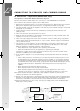
Cooker Stability
Note: To ensure cooker stability, both the anti-tilt plate and stability bolt MUST be installed on
all cookers (electric and gas).
Installation Sequence
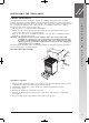
1. The cooker is delivered with the anti-tilt plate. Locate the anti-tilt plate against the rear wall. If
locating between 2 cupboards, then fit the plate in the centre of the space. If locating the
cooker at the end of a cupboard, then position the side of the plate 48mm from the cupboard.
Note: If cooker cannot be located against rear wall, move anti-tilt plate forward to suit.
2. Securely fix the anti-tilt plate to the floor with appropriate fasteners.
3. Slide the cooker back into the anti-tilt plate so that rear cover rests against the rear wall.
Then check the height and level of the cooker. If required, pull the cooker back out and adjust
the levelling feet as required.
4. Fasten the stability bolt bracket to the front frame with the 2 screws supplied.
5. Reposition the cooker back into the anti-tilt plate and then mark the position of the stability
bolt hole.
6. Pull the cooker back out and drill the bolt location hole. Use a 6.5mm masonry or wood drill.
When drilling into concrete ensure a minimum hole depth of 30mm.
7. Reposition the cooker back into the anti-tilt plate, aligning the stability bolt bracket with the
6.5mm drilled hole. Then slide the bolt through the bracket and into the hole.
8. Connect gas and electricity supply (refer to pages following).
9. Fit the kick panel bracket and kick panel onto the cooker.
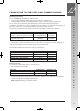
48mm to side
of bracket
Anti-Tilt Bracket
Rear Adjustable Foot
Cooker Width
600mm
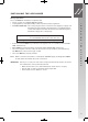
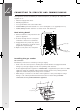
FITTING THE ANTI-TILT PLATE & STABILISING BOLT
Adjustable Feet
Stability Bolt
Stability Bolt Bracket
Kick-panel
Kick-panel Bracket
6.5mm Drilled
Location Hole
SIMPRD 342-1-529 30/1/08 8:51 AM Page 26