
Full Product Manual


Westinghouse Portable Power | 21
CHECKING AND ADJUSTING VALVE LASH
CAUTION
Checking and adjusting valve lash
must be done when the engine is cold.
1. Remove the rocker arm cover and carefully remove
the gasket. If the gasket is torn or damaged, it must
be replaced.
2. Remove the spark plug so the engine can be
rotated more easily.
3. Rotate the engine to top dead center (TDC) of the
compression stroke. Looking through the spark
plug hole, the piston should be at the top.
4. Both the rocker arms should be loose at TDC on
the compression stroke. If they are not, rotate the
engine 360°.
5. Insert a feeler gauge between the rocker arm and
the push rod and check for clearance (see Figure
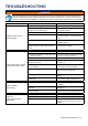
25). See table below for valve lash specications
Figure 25
(1) Push Rod, (2) Feeler Gauge Area
(3) Rocker Arm, (4) Jam Nut, (5) Adjusting Nut
Standard Valve Lash
Intake Valve Exhaust Valve
Valve Lash
0.0035 ± 0.0043 in
(0.09 ± 0.11 mm)
0.0043 ± 0.0051 in
(0.11 ± 0.13 mm)
Bolt Torque
8-12N.m 8-12N.m
6. If an adjustment is required, hold the adjusting nut
and loosen the jam nut.
7. Turn the adjusting nut to obtain the correct valve
lash. When the valve lash is correct, hold the ad-
justing nut and tighten the jam nut to 106 in-lb (12
N•m).
8. Recheck the valve lash after tightening the jam nut.
9. Perform this procedure for both the intake and
exhaust valves.
10. Install the rocker arm cover, gasket and spark plug.
MAINTENANCE
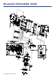
Figure 22: Remove screw holding spark arrestor
1
2
3
4
5
6. Slide the spark arrestor band clamp o the spark
arrestor screen.
7. Pull the spark arrestor screen o the muer
exhaust pipe (see Figure 23).
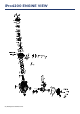
8. Using a wire brush, remove any dirt and debris that
may have collected on the spark arrestor screen
(see Figure 24).
9. If the spark arrestor screen shows signs of wear
(rips, tears or large openings in the screen), replace
the spark arrestor screen.
10. Install the spark arrestor components in the
following order:
a. Place spark arrestor screen over the muer
exhaust pipe. Push on the screen until it fully
bottoms out.
b. Place the spark arrestor band clamp over the
screen and tighten with a athead screwdriver
10. Replace the muer cover and the inverter cover
that you removed in step 4.
Figure 23: Remove spark arrestor
Figure 24: Brush dirt and debris o spark arrestor