MA7200 PLUS INVERTER SERIES FAN Quick Start Manual 3 to 75 HP Models- MA7200-2003-N1 Thru MA7200-2040-N1 (230V) & MA7200-4003-N1 Thru MA7200-4075-N1 (460V) Rev. 1.
MA7200 PLUS Inverter 3 to 75 HP Fan Quick Start Manual _______________________________________________________________ Quick Start Guide for Fan Applications This guide is to simplify the start up of the MA7200 PLUS Inverter series, 3 to 75 HP, for fan applications. It is not intended to replace the MA7200 PLUS Installation and Operation Manual, and the user is urged review this manual.
MA7200 PLUS Inverter 3 to 75 HP Fan Quick Start Manual _______________________________________________________________ Step 4 - Check Fan Motor Operation • Enter 10.00Hz for the frequency reference and set parameter Sn-08 = 1 to disable Reverse Direction operation. Note: The output from the inverter is displayed in Hz as factory default. If desired, the output may be displayed in per cent (%) of full speed.
MA7200 PLUS Inverter 3 to 75 HP Fan Quick Start Manual _______________________________________________________________ • Press the RUN key, and check the fan direction of rotation. If the direction is not correct, press the STOP key and wait until the fan has come to a complete STOP. Next, power down the inverter. Danger • After the power has been turned OFF, wait at least 5 minutes until the charge indicator extinguishes completely before touching any wiring, circuit boards or components.
MA7200 PLUS Inverter 3 to 75 HP Fan Quick Start Manual _______________________________________________________________ ______________________________________________________________ TECO – Westinghouse Motor Company 5
MA7200 PLUS Inverter 3 to 75 HP Fan Quick Start Manual _______________________________________________________________ • After the method of control has been selected, if external control wiring is required, (e.g. external analog) power down the inverter before removing any covers or making any connections. In the following pages are wiring examples for Start / Stop, E-Stop, Restart, and Analog Connections.
MA7200 PLUS Inverter 3 to 75 HP Fan Quick Start Manual _______________________________________________________________ DIGITAL INPUT / OUTPUT terminal connections ( 3 – 75 HP ) Fig’s 2a, 2b, and 2c below show the control terminal connections for input control functions. The connections shown are typical and the user is referred to the MA7200 PLUS Manual if additional information is required. Fig. 2d shows an example for the use of the Fault Output Relay.
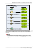
MA7200 PLUS Inverter 3 to 75 HP Fan Quick Start Manual _______________________________________________________________ ANALOG INPUT terminal connections ( 3 – 75 HP ) Fig’s 3a, 3b, and 3c.show the various analog input schemes that can be used to control the output frequency and thus the speed of the fan motor when External Analog is selected by Sn-05 in Step 5. Only one method may be used as the input source with Fig. 3a Potentiometer Input being most common.
MA7200 PLUS Inverter 3 to 75 HP Fan Quick Start Manual _______________________________________________________________ MA7200 PLUS BLOCK DIAGRAM Fig. 4 is an overall basic electrical connection diagram for MA7200 PLUS inverters rated 3 to 75 HP. It is used in conjunction with the other sections of this guide to give the user the ability to successfully start up a Fan application.
MA7200 PLUS Inverter 3 to 75 HP Fan Quick Start Manual _______________________________________________________________ Appendix AChanging display to read output speed in percent (%) of full speed. The display is factory defaulted to show the inverter output frequency in Hz. If desired, the display can be changed to show the output frequency as a percentage of full speed.
MA7200 PLUS Inverter 3 to 75 HP Fan Quick Start Manual _______________________________________________________________ Appendix B Removing the LCD Digital Operator and Inverter Cover(s) ______________________________________________________________ 11 TECO – Westinghouse Motor Company