
Instruction manual

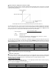
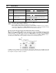
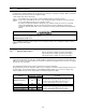

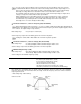

Table Of Contents
- Preface
- Safety Precautions
- Table of Contents
- Warnings, Cautions and Conformity
- Chapter 1 Drive Model Identification
- Chapter 2 Mounting and Wiring the Inverter
- Chapter 3 Operation using the Keypad
- Chapter 4 Function Codes / Parameters
- Chapter 5 Check Motor Rotation and Direction
- Chapter 6 Speed Reference Command Configuration
- Chapter 7 Operation Method Configuration (Run / Stop)
- Chapter 8 Motor and Application Specific Settings
- Chapter 9 Using PID Control for Constant Flow / Pressure Applications
- Chapter 10 Troubleshooting
- 10.1 Protective Functions
- 10.2 Before Proceeding with Troubleshooting
- 10.3 If Neither an Alarm Code Nor "Light Alarm" Indication Appears on the LED Monitor
- 10.4 If an Alarm Code Appears on the LED
- 10.5 If the “Light Alarm” Indication Appears on the LED Monitor
- 10.6 If an Abnormal Pattern Appears on the LED Monitor except Alarm Codes and "Light Alarm" Indication
- 10.7 If the Inverter is Running on Single-Phase Power
- Chapter 11 Specifications
4-38
Under vector control without speed sensor
Under vector control with speed sensor
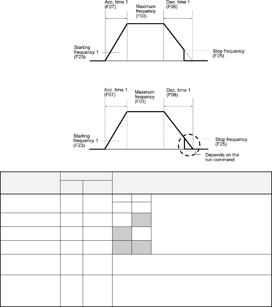
Acceleration/deceleration time
Acceleration/
deceleration time
Function code
Switching factor of acceleration/deceleration time
( Refer to the descriptions of E01 to E07.)
ACC
time
DEC
time
Acceleration/
deceleration time 1
F07
F08
RT1
RT2
The combinations of ON/OFF states of the
two terminal commands RT2 and RT1 offer
four choices of acceleration/deceleration
time 1 to 4.
(Data = 4, 5)
If no terminal command is assigned, only the
acceleration/deceleration time 1 (F07/F08) is
effective.
OFF
OFF
Acceleration/
deceleration time 2
E10
E11
OFF
ON
Acceleration/
deceleration time 3
E12
E13
ON
OFF
Acceleration/
deceleration time 4
E14
E15
ON
ON
At jogging operation
H54
H55
When the terminal command JOG is ON, jogging operation
is possible. (Data = 10)
( Refer to the description of C20.)
At forced stop
-
H56
When the terminal command STOP is OFF, the motor
decelerates to a stop in accordance with the deceleration
time for forced stop (H56). After the motor stops, the inverter
enters the alarm state with the alarm er6 displayed. (Data =
30)