
Instruction manual
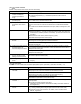
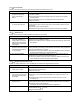
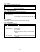
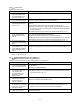
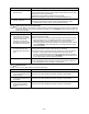
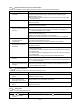
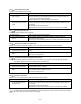
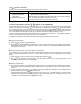
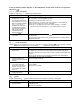
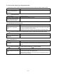
Table Of Contents
- Preface
- Safety Precautions
- Table of Contents
- Warnings, Cautions and Conformity
- Chapter 1 Drive Model Identification
- Chapter 2 Mounting and Wiring the Inverter
- Chapter 3 Operation using the Keypad
- Chapter 4 Function Codes / Parameters
- Chapter 5 Check Motor Rotation and Direction
- Chapter 6 Speed Reference Command Configuration
- Chapter 7 Operation Method Configuration (Run / Stop)
- Chapter 8 Motor and Application Specific Settings
- Chapter 9 Using PID Control for Constant Flow / Pressure Applications
- Chapter 10 Troubleshooting
- 10.1 Protective Functions
- 10.2 Before Proceeding with Troubleshooting
- 10.3 If Neither an Alarm Code Nor "Light Alarm" Indication Appears on the LED Monitor
- 10.4 If an Alarm Code Appears on the LED
- 10.5 If the “Light Alarm” Indication Appears on the LED Monitor
- 10.6 If an Abnormal Pattern Appears on the LED Monitor except Alarm Codes and "Light Alarm" Indication
- 10.7 If the Inverter is Running on Single-Phase Power
- Chapter 11 Specifications
10-23
[ 28 ] Speed mismatch or excessive speed deviation
Problem An excessive deviation appears between the speed command and the detected speed.
Possible Causes
What to Check and Suggested Measures
(1) Incorrect setting of function
code data.
Check the following function code data; P01* (Motor (No. of poles)), d15
(Feedback encoder pulse count/rev), and d16 and d17 (Feedback pulse
correction factor 1 and 2).
Specify data of function codes P01*, d15, d16, and d17 in accordance with
the motor and PG.
(2) Overload.
Measure the inverter output current.
Reduce the load.
Check whether any mechanical brake is working.
Release the mechanical brake.
(3) The motor speed does not
rise due to the current limiter
operation.
Check the data of function code F44 (Current limiter (Level)).
Change the F44 data correctly. Or, set the F43 data to "0" (Disable) if the
current limiter operation is not needed.
Check the data of function codes F04*, F05*, and P01* through P12* to ensure
that the V/f pattern setting is right.
Match the V/f pattern setting with the motor ratings.
Change the function code data in accordance with the motor parameters.
(4) Function code settings do
not match the motor
characteristics.
Check whether the data of P01*, P02*, P03*, P06*, P07*, P08*, P09*, P10* and
P12* match the parameters of the motor.
Perform auto-tuning of the inverter, using the function code P04*.
(5) Wrong wiring between the
pulse generator (PG) and
the inverter.
Check the wiring between the PG and the inverter.
Correct the wiring.
Check that the relationships between the PG feedback signal and the run
command are as follows:
For the FWD command: the B phase pulse is in the High level at rising edge of
the A phase pulse
For the REV command: the B phase pulse is in the Low level at rising edge of
the A phase pulse
If the relationship is wrong, interchange the A and B phase wires.
(6) Wiring to the motor is
incorrect.
Check the wiring to the motor.
Connect the inverter output terminals U, V, and W to the motor input terminals
U, V, and W, respectively.
(7) The motor speed does not
rise due to the torque limiter
operation.
Check the data of F40 (Torque limiter 1-1).
Correct the F40 data. Or, set the F40 data to "999" (Disable) if the torque
limiter operation is not needed.
[ 29 ] NTC wire break error
Problem A wire break is found in the NTC thermistor detection circuit.
Possible Causes
What to Check and Suggested Measures
(1) The NTC thermistor cable is
broken.
Check whether the motor cable is broken.
Replace the motor cable.
(2) The temperature around the
motor is extremely low
(lower than -30C (-22F)).
Measure the temperature around the motor.
Reconsider the use environment of the motor.
(3) The NTC thermistor is
broken.
Measure the resistance of the NTC thermistor.
Replace the motor.
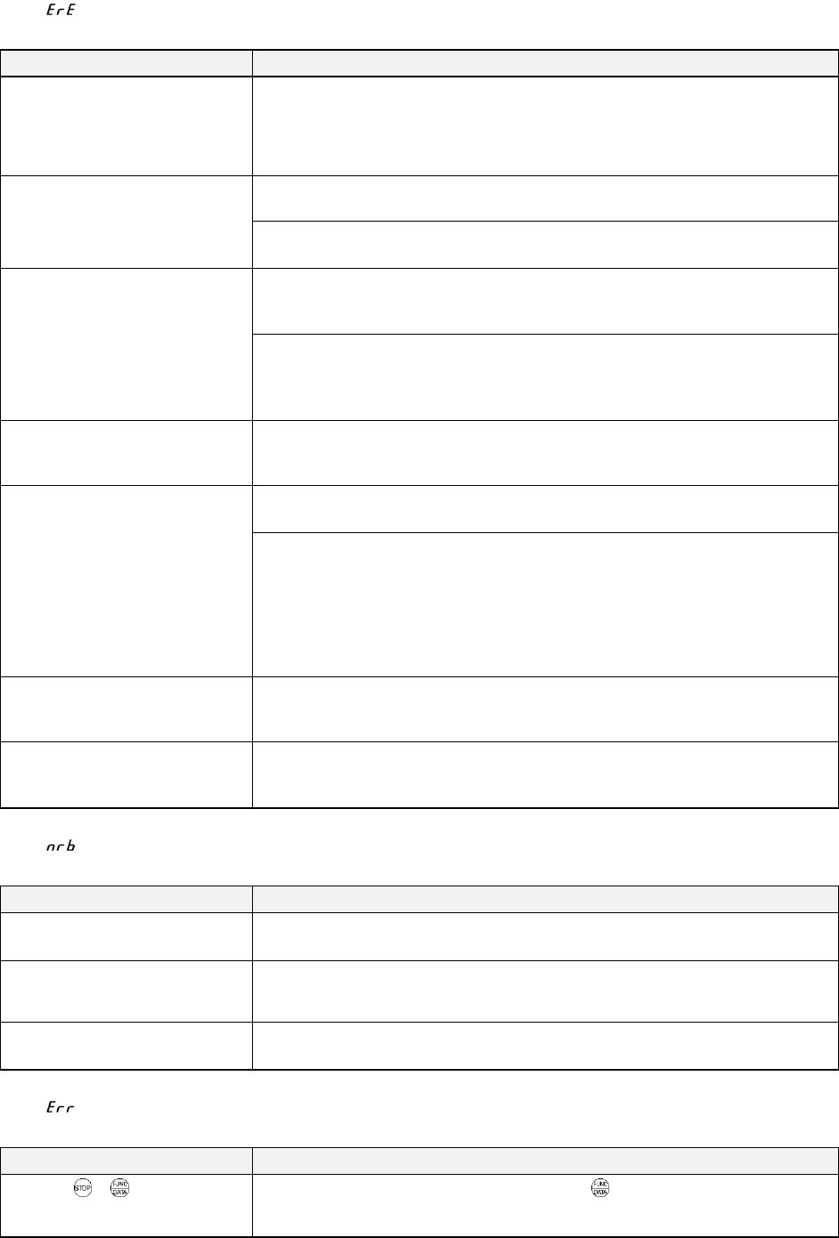
[ 30 ] Mock alarm
Problem The LED displays the alarm err.
Possible Causes
What to Check and Suggested Measures
(1) The + keys were held
down for more than 5
seconds.
To escape from this alarm state, press the key.