
Instruction manual

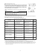
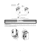
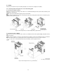
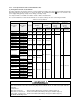
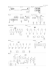
Table Of Contents
- Preface
- Safety Precautions
- Table of Contents
- Warnings, Cautions and Conformity
- Chapter 1 Drive Model Identification
- Chapter 2 Mounting and Wiring the Inverter
- Chapter 3 Operation using the Keypad
- Chapter 4 Function Codes / Parameters
- Chapter 5 Check Motor Rotation and Direction
- Chapter 6 Speed Reference Command Configuration
- Chapter 7 Operation Method Configuration (Run / Stop)
- Chapter 8 Motor and Application Specific Settings
- Chapter 9 Using PID Control for Constant Flow / Pressure Applications
- Chapter 10 Troubleshooting
- 10.1 Protective Functions
- 10.2 Before Proceeding with Troubleshooting
- 10.3 If Neither an Alarm Code Nor "Light Alarm" Indication Appears on the LED Monitor
- 10.4 If an Alarm Code Appears on the LED
- 10.5 If the “Light Alarm” Indication Appears on the LED Monitor
- 10.6 If an Abnormal Pattern Appears on the LED Monitor except Alarm Codes and "Light Alarm" Indication
- 10.7 If the Inverter is Running on Single-Phase Power
- Chapter 11 Specifications
1-11
High-speed motors
If the reference frequency is set to 120 Hz or higher to drive a high-speed motor, test-run the combination of the
inverter and motor beforehand to check it for the safe operation.
Precautions for use on single-phase power
An inverter is a device that converts alternating current of the input line to direct current via the ac-to-dc rectifier and
then converts it to alternating current via the dc-to-ac switching inverter circuit in order to output the required
alternating current. The EQ7 drive is designed to connect to the three-phase power and this manual stipulates the
specifications for the use on the three-phase power.
If the inverter designed for connection to three-phase power runs on single-phase power, ripples (voltage fluctuation)
on the DC link bus voltage rectified from the input power become larger than those in the inverter running on three-
phase power. The DC-voltage ripple affects the inverter output; that is, ripples could be superimposed on the output
voltage or current, making control hard.
Accordingly, the inverter may not work in full performance or function correctly. To use the EQ7 drive on single-phase
power, therefore, you need to take the following into account.
Output current
Select the inverter capacity to keep the output current within the specified level, referring to chapter 11. Output current
exceeding the limit extremely increases voltage ripples on the DC link bus, impeding normal operation or resulting in
an inverter breakdown.
Wiring
When connecting 230 V inverters of 60 HP or above or 460 V ones of 125 HP or above to single-phase power, use L1
and L3 phases since cooling fans and magnetic contactors inside the inverter are supplied with power via L1 and L3.
Using L2 does not work cooling fans or magnetic contactors, causing abnormal heat, in the worst case, resulting in an
inverter breakdown.
Connecting peripheral devices
For the specifications of circuit breakers and fuses to apply, refer to pages 1-6 and 1-7.
Configuring function codes
(1) Cancel the input phase loss protection of the protection/maintenance function with function code H98 (Bit 1 = 0).
This is because the inverter judges single-phase power as a phase loss.
(2) Limit the drive mode to the VT / CT-V mode (Function code F80 = 0 or 1).
(3) Do not use "Vector control without speed sensor" or torque control. (Function codes F42 5, H18 = 0)
(4) "V/f control with slip compensation inactive" is recommended (F42 = 0). Any other drive control calculates the
motor model using the motor parameters inside the inverter. As ripples on the DC link bus voltage become larger,
therefore, calculation causes some errors so that the inverter may not provide the desired performance. Consider
this problem before use. In particular, when using "Vector control with speed sensor" (F42 = 6), dancer control
(J01 = 3), or brake signals (J68, J69, J70, etc.), assure the operation and safety of those speed sensors.