
Instruction manual
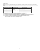
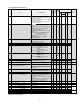
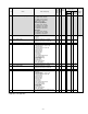
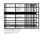
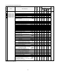
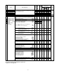
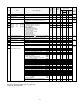
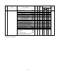
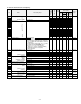
Table Of Contents
- Preface
- Safety Precautions
- Table of Contents
- Warnings, Cautions and Conformity
- Chapter 1 Drive Model Identification
- Chapter 2 Mounting and Wiring the Inverter
- Chapter 3 Operation using the Keypad
- Chapter 4 Function Codes / Parameters
- Chapter 5 Check Motor Rotation and Direction
- Chapter 6 Speed Reference Command Configuration
- Chapter 7 Operation Method Configuration (Run / Stop)
- Chapter 8 Motor and Application Specific Settings
- Chapter 9 Using PID Control for Constant Flow / Pressure Applications
- Chapter 10 Troubleshooting
- 10.1 Protective Functions
- 10.2 Before Proceeding with Troubleshooting
- 10.3 If Neither an Alarm Code Nor "Light Alarm" Indication Appears on the LED Monitor
- 10.4 If an Alarm Code Appears on the LED
- 10.5 If the “Light Alarm” Indication Appears on the LED Monitor
- 10.6 If an Abnormal Pattern Appears on the LED Monitor except Alarm Codes and "Light Alarm" Indication
- 10.7 If the Inverter is Running on Single-Phase Power
- Chapter 11 Specifications

4-4
Code
Name
Data setting range
Change when
running
Data
copying
Default
setting
Drive control
Refer to
Page
V/f
Vector
Control
w/
PG
Torque
control
w/o
PG
F26
Motor Sound (Carrier frequency)
Variable Torque Models
0.5 to 30HP: 0.75 to 16 KHz
40 to 100HP: 0.75 to 10 KHz
125 to 900HP: 0.75 to 6 KHz
1000HP: 0.75 to 4 KHz
Constant Torque Models
0.5 to 75HP: 0.75 to 16 KHz
100 to 125HP: 0.75 to 10 KHz
150 to 700HP: 0.75 to 2 KHz
800 to 900HP: 0.75 to 6 KHz
CT-V Models
0.5 to 75HP: 0.75 to 16 KHz
100 to 700HP: 0.75 to 10 KHz
800 to 900HP: 0.75 to 6 KHz
Y
Y
2KHz
Y
Y
Y
Y
4-54
F27
Motor Sound (Tone)
0: Level 0 (Inactive)
1: Level 1
2: Level 2
3: Level 3
Y
Y
0
Y
N
N
Y
4-54
F29
Analog Output [FM1]
(Mode selection)
0: Output in voltage (0 to 10 VDC)
1: Output in current (4 to 20 mA DC)
2: Output in current (0 to 20 mA DC)
Y
Y
0
Y
Y
Y
Y
F30
(Voltage adjustment)
0% to 300%
Y*
Y
100
Y
Y
Y
Y
F31
(Function)
Select a function to be monitored from the
followings.
0: Output frequency 1 (before slip
compensation)
1: Output frequency 2 (after slip
compensation)
2: Output current
3: Output voltage
4: Output torque
5: Load factor
6: Input power
7: PID feedback amount (PV)
8: PG feedback value
9: DC link bus voltage
10: Universal AO
13: Motor output
14: Calibration (+)
15: PID command (SV)
16: PID output (MV)
Y
Y
0
Y
Y
Y
Y
17: Positional deviation in synchronous run
mode
N
N
Y
N
F32
Analog Output [FM2]
(Mode selection)
0: Output in voltage (0 to 10 VDC)
1: Output in current (4 to 20 mA DC)
2: Output in current (0 to 20 mA DC)
Y
Y
0
Y
Y
Y
Y
F34
(Voltage adjustment)
0% to 300%
Y*
Y
100
Y
Y
Y
Y
F35
(Function)
Select a function to be monitored from the
followings.
0: Output frequency 1 (before slip
compensation)
1: Output frequency 2 (after slip
compensation)
2: Output current
3: Output voltage
4: Output torque
5: Load factor
6: Input power
7: PID feedback amount (PV)
8: PG feedback value
9: DC link bus voltage
10: Universal AO
13: Motor output
14: Calibration (+)
15: PID command (SV)
16: PID output (MV)
Y
Y
0
Y
Y
Y
Y
17: Positional deviation in synchronous run
mode
N
N
Y
N
The shaded function codes are applicable to the quick setup.
Y: Applicable / N: Not Applicable.