
Technical information


4.3.6 Microwave ‘Preselector” Filter
Switches S5 and S6 are controlled by the WSP when on-line to select the microwave
bandpass filter (FL3 or PL4) matched to the active channel transmitter frequency.
4.3.7 RF Receive Chain Output
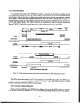
As shown in figure 10, the RF receiving chain components of the ASR-9’s six level weather
channel are shared by the WSP. When on-line, the WSP RDA sets switch XSW107 to direct this
output to the WSP’s high dynamic range II? receiver.
4.3.8 Sensitivity Time Control Attenuator
The STC unit within the shared WSP/Six-Level Weather Channel RF train is controlled by
the RDA when the WSP is on-line. As noted, the WSP normally employs significantly less
attenuation than is used by the existing weather channel owing to the increased dynamic range of
its IP receive chain and digitization circuits. The RDA controls the STC unit on a range-azimuth
dependent basis using site-adaptable maps. Eight STC maps are employed to cover all
combinations of polarization (CP or LP), active channel (A or B) and beam selection (high or
low).
4.3.9 Six-Level Data Output Selection
The six-level weather feed to the local maintenance PPI display, and to controller’s DEDS
and BRITE display is switched to the on-line processor, i.e., either the WSP or the ASR-9 six-
level output ports. The switch function is installed by cutting four wires on the backplane and
installing appropriate SPDT logic to route either the WSP output, suitably formatted and
controlled, or the original ASR-9 six-level weather data to the transmission circuits of the
ASR-9. Refer to T16310.36 card #216 and card #llO, appendix X 645A196-1 rev. AG sheet
#126 [RXD3T(+/-) and RTS (+/-)I. [Note: This reference is optional as there may be less
invasive use of the backplane wiring. The above mentioned circuit revisions communicate only
six-level weather information from the. WSP or the ASR-9 weather channel to the controller’s
ARTS display processor via circuits MIP and SCIP already in place in the ASR-9. Separate
circuits that combine the product generator outputs are used to feed the dedicated WSP display
functions in the TRACON and the ATCT.]
4.3.10 “Off-line” or ‘Fault” Condition
If the WSP is placed off-line due to detection of a fault condition by its RMS, or through user
manual action, microwave switches must be latched in appropriate positions and ASR-9 system
control functions restored so that baseline ASR-9 system functions and operation are unaffected.
These default switch positions shall correspond to the unenergized state. The following actions
are required:
1. Switches XSW 101 and XSW 102 are latched so as to “hardwire” the same sense
polarization low beam antenna outputs to the input of the target channel RAG
beam switches (S2 and S3).
34