
Use And Care Manual


whl-648 Rev. 000 Rel. 003 Date 3.6.18
51
K. 0-10 Volt Input
1. A signal from a building management system may be connected to the appliance to enable remote control. This signal should be a
0-10 volt positive-going DC signal. When the 0-10V input is wired to the appliance terminal strip, a building control system can be used
to control the set point temperature of the appliance. The control interprets the 0-10 volt signal as follows; when the signal is between 0
and 1.5 volts, the appliance will be in standby mode, not ring. When the signal rises above 1.5 volts, the appliance will ignite. As the signal
continues to rise towards its maximum of 10 volts, the appliance will increase in set point temperature.
2. Connect a building management system or other auxiliary control signal to the terminals marked for this purpose on the appliance
terminal block (shown in Piping Diagrams, this manual). Caution should be used to ensure that the 0-10 VOLT + connection does not
become connected to ground.
NOTE: Ensure that the polarity of the connections from the external modulating appliance controller to the appliance is correct. Reversed
polarity could lead to erratic and/or no response from the appliance controller.
NOTE: Outdoor Temperature Mode Icon on the display will ash if an Outdoor Sensor or 0-10 Volt is not connected to the appliance.
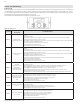
0-10 V INPUT TABLE:
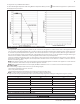
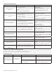
When outside voltage is applied to the connector (2) in the wiring diagram,
1. The outdoor temperature sensor does not work.
2. The 0-10V symbol is displayed.
3. The heating temperature is automatically set according to the external voltage input.
NOTE: 0-10V is prioritized over T/T. If input voltage is less than 1.5V then T/T will operate.
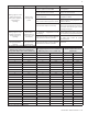
The range of input voltage is approximately 1.5[V] ~ 10[V] and the heating temperature settings according to this range are as follows.
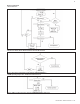
Figure 48 - Outdoor Reset Curve - See Installer Mode for Curve Setting Descriptions
Input voltage[V] Heat temperature [
o
C] Heat temperature [
o
F]
1.5 35.0 95
2.0 37.1 98.8
2.5 39.2 102.7
3.0 41.3 106.5
…
9.0 66.6 152
9.5 69 156.2
10 71.1 160
Table 29 - 0-10V Input Voltages and Associated Temperatures
Voltage exceeding 15V may damage internal parts. Such damages are not covered by product warranty.
See Figure 48 to set your Outdoor Reset Curve.
To check the CH Target Temperature while using Outdoor Temperature Mode, press the
button while the appliance is operational and
the display panel is powered on.