
Warranty


whl-648 Rev. 001 Rel. 000 Date 4.11.19
32
E. Exhaust Vent and Intake Pipe Sizing
1. The exhaust vent and intake pipe size is 3”.
2. The total equivalent length of 2” exhaust vent and intake pipe should
not exceed fty (50) feet; 3” exhaust vent and intake pipe should not
exceed one hundred (100) feet.
a. The equivalent length of elbows, tees, and other ttings are
listed in the Friction Loss Table.
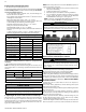
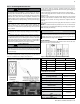
Friction Loss Equivalent in Piping and Fittings
Fittings or Piping
Equivalent Feet
2” 3”
90 Degree Elbow* 5’ 5’
45 Degree Elbow 3’ 3’
Coupling 0’ 0’
Air Inlet Tee 0’ 0’
Straight Pipe 1’ 1’
Concentric Kit 3’ 3’
V500 2” Kit 1’ N/A
V1000 3” Kit N/A 1’
V2000 4” Kit N/A 1’
Table 15 - *Friction loss for long radius elbow is 1 foot less. NOTE: Consult
Polypropylene venting instructions for friction loss and pressure drop
equivalents.
b. For example: If the exhaust vent has two 90
o
elbows and 10 feet
of PVC pipe we will calculate:
Exhaust Vent Equivalent Length = (2x5) + 10 = 20 feet.
Further, if the intake pipe has two 90
o
elbows, one 45
o
elbow, and
10 feet of PVC pipe, the following calculation applies:
Intake Pipe Equivalent Length = (2x5) + 3 + 10 = 23 feet.
Finally, if a concentric kit is used we nd:
Total Equivalent Length = 20 + 23 + 3 = 46 feet.
The total equivalent length is 46 feet, well below the maximum of
150 feet.
c. Eort should be made to keep a minimum dierence in
equivalent length between the exhaust vent and intake pipe.
3. The minimum total equivalent length is 14 feet.
NOTE: The intake pipe and exhaust vent lengths do not have to be of
equal length. There is no balancing requirement between intake and
exhaust.
2” Combined Vent Length 3” Combined Vent Length
Minimum Maximum Minimum Maximum
14’ (4.2M) 50’ (15M) 14’ (4.2M) 100’ (30M)
Maximum # of 90
o
Elbows
(2” and 3” Vent Diameters)
6
Table 16 - Approved Vent Lengths
Do not exceed the maximum lengths for vent pipes. Excessive length
could result in boiler shutdown and property damage.
CAUTION
Failure to provide a minimum total vent length of 14 equivalent feet
could result in property damage and improper product operation.
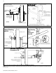
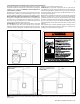
F. Tightening Boiler Collar to Exhaust Vent and Intake Pipe
This boiler uses 2” or 3” diameter pipe for exhaust vent and intake pipe.
In order to use 2” pipe, it is required to reduce pipe size in a vertical
length of pipe with a 3” x 2” reducing coupling (not included). Follow
the steps below to install 3” vent pipe into the boiler vent collar. See
Figure 19 for additional details.
Figure 19 - Correct Installation into the Boiler Collar
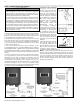
Figure 20 - Transitioning from 3” to 2” Vent Pipe
WARNING
!
Failure to install the included 6” length of 3” CPVC pipe in the
exhaust vent adapter before transitioning to other vent materials
could result in property damage, severe personal injury, or death.
G. Exhaust Vent and Intake Pipe Installation
All joints of positive pressure vent systems must be sealed
completely to prevent leakage of ue products into the living
space. Failure to do so could result in property damage, serious
injury, or death.
WARNING
!
1. Use only solid PVC, CPVC, or stainless steel pipe or a Polypropylene
vent system approved for use with Category IV appliances.
ABS pipe material may be used on air intake piping only.
2. Remove all burrs and debris from joints and ttings.
3. When using PVC or CPVC pipe, all joints must be properly cleaned,
primed, and cemented. Use only cement and primer approved for
use with the pipe material. Cement must conform to ASTM D2564
for PVC and ASTM F493 for CPVC pipe. NOTE: DO NOT CEMENT
POLYPROPYLENE PIPE.
4. Ensure the vent is located where it will not be exposed to
prevailing winds.
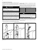
5. In all roof venting applications, exhaust discharge must point
away from the pitch of the roof.
6. To prevent water leakage, install adequate roof ashing where the
pipe enters the roof.
7. Do not locate vent over public walkways, driveways, or parking
lots. Condensate could drip and freeze, resulting in a slip hazard or
damage to vehicles and machinery.
8. Due to potential moisture build-up, sidewall venting may not
be the preferred venting option. To save time and cost, carefully
consider venting installation and location.
9. Horizontal lengths of exhaust vent must slope back towards the
boiler not less than ¼” per foot to allow condensate to drain from
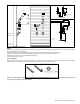
NOTE: Clean and dry the boiler connection. DO NOT use primer or
cement on the boiler connection.
1. Push the length of pipe into the connection until it touches
the bottom of the tting.
2. Tighten the clamps using a screwdriver.
3. Ensure the pipe is secure before continuing installation.
4. For 2” installations, install the reducing coupling in a vertical
section of pipe. At least a 6” length of 3” pipe MUST BE
INSTALLED before reducing to 2”. See Figure 20.
NOTE: A reducing coupling MUST BE USED when transitioning
from 3” to 2” vent pipe. DO NOT use reducing bushings.