Gas Fired Residential Floor and Wall Mount Combi Boilers Installation Start-Up Maintenance Parts Warranty WBRC**140 / 199* WBRUC**140 / 199* Models * “F” Denotes Floor Model; “W” Denotes Wall Mount Model, ** “NG” Denotes Natural Gas; “LP” Denotes Propane Gas Heat Exchanger Bears the ASME “H” Stamp This manual must only be used by a qualified service technician. Read all instructions in this manual before installing. Perform steps in the given order.
WARNING: If the information in these instructions is not followed exactly, a fire or explosion may result causing property damage, personal injury or death. t Do not store or use gasoline or other flammable vapors and liquids in the vicinity of this or any other appliance. WHAT TO DO IF YOU SMELL GAS t Do not try to light any appliance. t Do not touch any electrical switch; do not use any phone in your building. t Immediately call your gas supplier from a neighbor’s phone.
Foreword For the Installer This manual is intended to be used in conjunction with other literature provided with the appliance. This includes all related control information. It is important that this manual, all other documents included in this system, and additional publications including the Code for the Installation of Heat Producing Appliances and National Fuel Gas Code - ANSI Z223.1 (latest versions), be reviewed in their entirety before beginning any work.
The hydronic supply and return connections of these products are for installation in closed loop systems ONLY! Use of this product in any manner other than described in this manual may result in premature product failure, substantial property damage, severe personal injury, or death. Damage or failure of this product (or the system in which it is installed) due to unauthorized use IS NOT COVERED BY WARRANTY.
Part 5 - Venting A. General B. Approved Materials for Exhaust Vent and Intake Pipe C. Additional Requirements for Installation in Canada D. Exhaust Vent and Intake Pipe Location E. Exhaust Vent and Intake Pipe Sizing F. Tightening Appliance Collar to Exhaust Vent and Intake Pipe G. Exhaust Vent and Intake Pipe Installation H. Applications 1. Direct Vent Installation of Exhaust and Intake 2. Venting Through an Existing System 3.
This appliance must be installed by a qualified service technician. Improper installation and/or operation can cause a potentially hazardous situation, which, if not avoided, could result in serious injury or death, and will void the warranty. The manufacturer cannot anticipate every circumstance that might involve a potential hazard. Each installation has its own specialized characteristics, requirements, and possible hazards. Therefore, all possible incidents are not included in these warnings.
D. When Servicing the Appliance Be sure to disconnect electrical power before opening appliance cabinet or performing service. Label all wires while performing service to ensure proper re-wiring of the appliance. Wiring errors can cause improper or dangerous operation. Failure to do so could result in an electrical shock, improper appliance operation, property damage, serious personal injury, or death.
H. Water Temperature Adjustment and Scalding This appliance can deliver scalding water. Be careful whenever using hot water to avoid scalding injury. Certain appliances such as dishwashers and automatic clothes washers may require increased water temperatures. By setting the thermostat on this heater to obtain the increased water temperature required by these appliances you may create the potential for scald injury. To protect against injury, install a mixing valve in the water system.
Part 2 - Before You Start Open the shipping crate of the appliance. UNCRATING THE APPLIANCE - Any claims for damage or shortage in shipment must be filed immediately against the transportation company by the consignee. A.
t Condensate Removal Pump (Part # 554200) t 2” Mesh Vent Screens (Part # 7850P-088) t UL353 Low Water Cut-Off Kit (Part # 7855P-315) NOTE: When using an optional system sensor, pipe insulation must be wrapped around it to improve temperature measurement accuracy and increase overall system efficiency. Part 3 - Prepare the Appliance Installation Remove all sides of the shipping crate to allow the appliance to be moved into its installation location.
All appliances eventually leak. It is recommended to install a catch pan beneath the appliance. This catch pan should be sized with a maximum depth of 2”, and a minimum diameter 2” greater than the diameter of the appliance. The catch pan should empty into an open drain line. This drain line should be 3/4” ID minimum, piped to an open drain. Failure to follow these instructions could result in property damage. Such damages ARE NOT covered by product warranty.
Vents must be properly supported. Appliance exhaust and intake connections are not designed to carry heavy weight. Vent support brackets must be within 1’ of the appliance and the balance at 4’ intervals. Appliance must be readily accessible for visual inspection for first 3’ from the appliance. Failure to properly support vents could result in property damage, severe personal injury, or death. The exhaust discharged by this appliance may be very hot.
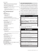
Products to Avoid Areas Likely to Have Contaminants Spray cans containing fluorocarbons Dry cleaning / laundry areas and establishments Permanent wave solutions Swimming pools Chlorinated waxes / cleaners Metal fabrication plants Chlorine-based swimming pool chemicals Beauty shops Calcium chloride used for thawing Refrigeration repair shops Sodium chloride used for water softening Photo processing plants Refrigerant leaks Auto body shops Paint or varnish removers Plastic manufacturing pl
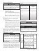
I. Technical Specifications Model 140 Installation Minimum / Maximum Input (Btu/Hr) 199 Indoor, Wall Mounted Model or Floor Model, Fully Condensing Central Heating (CH) Domestic Hot Water (DHW) 19,900 / 140,000* 14,000 / 140,000 19,900 / 199,000* Flue System Category IV, Sealed Combustion Direct Vent, Power Vent Vent Run 2” (50 feet), 3” (100 feet), Schedule 40 PVC, CPVC, PP AFUE 96% 95% oF Rise 35 7.1 GPM 9.9 GPM 45oF Rise 5.5 GPM 7.7 GPM 77o 3.2 GPM 4.
Figure 3 - Wall Mount Model Dimensions Description Diameter A Automatic Air Vent - B Air Intake Adapter C Exhaust Vent Adapter D Pressure Relief Valve Adapter E CH Supply Adapter F CH Return Adapter G DHW Outlet Adapter H DHW Inlet Adapter I K L M 140 17.3 34 15.4 3/4” NPTF 1” NPT 3/4” NPT Gas Inlet Adapter J Table 9 - Adapter Specifications - All Models Model 3” N Condensate Adapter 1/2” NPT (3/4” PVC Socket on Floor Models) O P Q R S T U V 6.7 4.3 2.8 5.
Figure 4 - Floor Model Dimensions Model K L M N O P Q R 140 17.3 19.1 16.8 12 9.5 7 5.3 3 199 19.7 21.5 18.2 13.3 10.8 8.3 6.6 4.3 S T U V W X Y 2.5 4 5 6.5 7.3 9.5 13.5 Z AA AB AC AD AE AF 44.8 12 7.4 4.7 6.8 12.6 5.5 48 14 8.5 3.2 9.2 15.1 5.2 Table 11 - Floor Model Specifications and Dimensions the modulating range to ensure high reliability. The burner is constructed of durable ceramic metal fiber for long service life.
Figure 5 - Components Number Component Description Number Component Description Number Component Description 1 Air Vent 11 CH Return Adapter 21 Control Panel 2 Relief Valve Adapter 12 CH Pressure Gauge 22 Heat Exchanger 3 Air / Gas Mixing Pipe 13 DHW Outlet Adapter 23 Ignition Transformer 4 Gas Valve 14 Gas Inlet Adapter 24 Flame Detecting Sensor 5 Internal Storage Tank 15 DHW Inlet Adapter with Filter and Flow Restrictor 25 BLDC Fan 6 Main PCB 16 Condensate Adapt
This appliance is too heavy for one person to lift. It is highly recommended to install the appliance with two people. Use caution as to not drop the appliance, which could damage the appliance and cause property damage and/or severe personal injury. Verify that the appliance is properly and securely mounted before leaving unsupervised. Failure to comply with the above and properly mount the appliance could result in substantial property damage, severe personal injury, or death.
Figure 8 - Water Pressure vs. Flow through the Restrictors - 140 Models Figure 9 - Water Pressure vs. Flow through the Restrictors - 199 Models Part 4 - Water Piping A. General Plumbing Guidelines Failure to follow the instructions in this section WILL VOID the warranty and may result in property damage, severe personal injury, or death. Do not apply a torch within 12” of the appliance.
Pipe material must be suitable to meet local codes and industry standards. t The pipe must be cleaned and without blemish before any connections are made. t The size of the DHW pipes should be 3/4” diameter, and the CH pipes should be 1” diameter. t Isolation (shutoff valves) should be used on both the CH and DHW loops to ease future servicing. t All piping should be insulated. It is recommended to install a sweat shut-off valve and a union in the return and supply piping to ease future servicing.