
Installation Manual

15
WHL-016 REV. 3.4.15
D. RESIDENTIAL GARAGE, CLOSET, AND ALCOVE INSTALLATIONS
Check with your local Authority Having Jurisdiction for requirements when installing boiler in a garage, closet, or alcove. Please read
the entire manual before attempting installation. Failure to properly take factors such as boiler venting, piping, condensate removal, and
wiring into account before installation could result in wasted time, money, and possible property damage and personal injury.
PRECAUTIONS
If the boiler is located in a residential garage, it should be installed per the latest edition of the National Fuel Gas Code, ANSI Z223.1,
and CGA-B149 Installation Code in Canada.
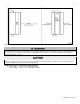
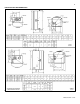
Mount the bottom of the boiler a minimum of 18” above the floor of the garage, to ensure the burner and ignition devices are
well off the floor.
Locate or protect the boiler so it cannot be damaged by a moving vehicle.
For closet or alcove installations, a two pipe venting system must be used. Failure to follow this warning could result in substantial
property damage, severe personal injury, or death.
The space must be provided with correctly sized combustion/ventilation air openings for all other boilers located in the space with the
boiler. Do not install the boiler in an attic. Failure to comply with these warnings could result in substantial property damage, severe
personal injury, or death.
NOTE: For installations using room air for combustion, refer to the boiler venting section, Part 6 in this manual.
E. EXHAUST VENT AND INTAKE PIPE
The appliance is rated ANSI Z21.13 Category IV (pressurized vent, likely to form condensate in the vent) and requires a special vent
system designed for pressurized venting.
NOTE: The venting options described here (and further detailed in the Venting section of this manual) are the lone venting
options approved for this appliance. Failure to vent the appliance in accordance with the provided venting instructions will
void the warranty.
Failure to vent the appliance properly will result in serious personal injury or death.
Vents must be properly supported. Appliance exhaust and intake connections are not designed to carry heavy weight. Vent support
brackets must be within 1’ of the appliance and the balance at 4’ intervals. Appliance must be readily accessible for visual inspection for
the first 3’ from the appliance.
1. DIRECT VENT INSTALLATION OF EXHAUST VENT AND INTAKE PIPE
If installing a direct vent option, combustion air must be drawn from the outdoors directly into the appliance intake, and exhaust must
terminate outside. There are three basic direct vent options detailed in this manual: 1. Side Wall Venting, 2. Roof Venting, and 3.
Unbalanced Venting.
Be sure to locate the appliance such that the exhaust vent and intake piping can be routed through the building and properly
terminated. Different vent terminals can be used to simplify and eliminate multiple penetrations in the building structure (see Optional
Equipment in Venting Section). The exhaust vent and intake piping lengths, routing and termination methods must all comply with the
methods and limits given in the Venting section of this manual.
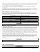
When installing a combustion air intake from outdoors, care must be taken to utilize uncontaminated combustion air. NOTE: To
prevent combustion air contamination, see Table 2.
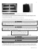
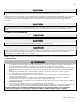
2. INDOOR COMBUSTION AIR INSTALLATION IN CONFINED OR UNCONFINED SPACE
This appliance requires fresh, uncontaminated air for safe operation and must be installed in a mechanical room where there is
adequate combustion and ventilating air. NOTE: To prevent combustion air contamination, see Table 2.
Combustion air from the indoor space can be used if the space has adequate area or when air is provided through a duct or louver to
supply sufficient combustion air based on the appliance input. Never obstruct the supply of combustion air to the appliance. If the