INSTALLATION MANUAL MODULAR REFRIGERATOR CONNECTION KIT WRB5004SA, WRB5004WA, WFB4204SA, WFB4204WA
CONGRATULATIONS CONTENTS Congratulations and thank you for choosing our connection kit. Before you install the connection kit, we recommend that you read through the entire installation manual. General warnings.................................................................................3 To avoid the risks that are always present when you install an electrical appliance, it is important that the kit and appliance is installed correctly.
GENERAL WARNINGS BEFORE YOU BEGIN lease read the user manual carefully and store in a handy P place for later reference. Pass the user manual on to possible new owners of the appliance. • Thoroughly inspect cabinets for any signs of damage before commencing installation. NOTE: Please refer to your Appliance User Manual for warnings relating to the appliance. • If any damage is identified please contact Electrolux Service.
CONNECTION KIT ITEMS This connection kit is designed for use on single door refrigerators and freezers whose total body height is 1725 mm.
JOINED DIMENSIONS 50mm 50mm 50mm 50mm 30mm CABINET CABINET DOOR DOOR 63mm Wa D D D1 D1 63mm 30mm 30mm 30mm CABINET 30mm Please note: Please note: Wa Doors are Doors designed are designed Minimum Minimum Minimum Minimum recommended recommended recommended recommended to sit proud to of sit proud of airspace airspace airspace airspace cabinetry cabinetry (not flush).(not flush).
CONNECTION KIT PACKAGE CONTENTS ITEM 1 DESCRIPTION Top-front bracket QTY. 1 2 ANC Grey White A03972801 1460583 A03972802 1460583 Self tapping screw 1 3 Bottom rear bracket 1 A03979601 4 Replacement screw ST4.
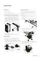
INSTALLATION Required Tools Fitting rear levelling feet • 3mm Allen key NOTE: Two people may be required for this operation • Phillips head screwdriver A set of adjustable back feet is provided with the kit. These parts are usually needed only in the case of a particularly • 7mm socket wrench screwdriver uneven floor and when height adjustments in phase 1.2.1 proved unsuccessful.
INSTALLATION Joining the Appliances Your appliances are delivered with hole covers that cover the screw holes. These holes are located on the top of the cabinet, opposite from the door hinge. Carefully remove these covers, care must be taken to avoid damaging the appliances. Carefully pull the appliances together adjacent to the final installation location, then adjust the front and rear feet to the same height.
ADJUSTING DOOR ALIGNMENT Extract the tensioner Fit bottom first Fit bottom first Tighten all the screws Lift top-front bracket Lift top-front bracket Tighten all screws To complete installation of your joined appliances it may be necessary to slightly adjust door alignment on the Tighten all individual appliance. This process screws is illustrated in the following section. 1. With the door open, remove the hinge cover by simultaneously pulling the cover away and up from the hinge.
NOTES 10 NOTES
NOTES NOTES 11
For more information on all Westinghouse appliances, or for dimension and installation information, call into your retailer, phone or email our customer care team or visit our website: AUSTRALIA phone: 1300 363 640 fax: 1800 350 067 email: customercare@electrolux.com.au web: westinghouse.com.au NEW ZEALAND phone: 0800 436 245 fax: 0800 225 088 email: customercare@electrolux.co.nz web: westinghouse.co.