USER MANUAL 900mm COOKING APPLIANCES WFE912SA WFE914SA WFE916SA WFE946SA WVE916SA
CONGRATULATIONS CONTENTS Congratulations and thank you for choosing our product. We are sure you will find your new appliance a pleasure to use and a great asset to your cooking. Before you use the appliance, we recommend you read through the whole user manual which provides a description of the product and its functions.
IMPORTANT SAFETY INSTRUCTIONS These warnings have been provided in the interest of safety. You MUST read them carefully before installing or using the appliance.
IMPORTANT SAFETY INSTRUCTIONS CERAMIC COOKTOPS WARNING OVEN During use the appliance becomes hot. Care should be taken to avoid touching the hot surfaces inside the oven. Switch the appliance off before removing the oven light glass for globe replacement. To avoid an accident, ensure that oven shelves and fittings are always inserted into the appliance in accordance with the instructions. Do not use the door as a shelf. Do not push down on the open oven door.
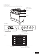
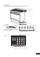
MODEL WFE912SA Gas hob, multi-function electric oven with electronic timer Removable wok trivet Stainless steel splashback (optional to fit) Removable cast iron trivet Gas burner Control panel Oven door Control Panel OFF OFF OFF OFF OFF COOK BAKE Oven function selector Oven temperature control HI HI HI HI HI LO LO LO LO LO Clock/Timer display Gas hob burner controls Medium heat burner Gas Hob Low heat burner High heat burner Intense heat wok burner 5 DESCRIPTION
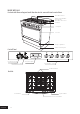
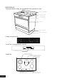
MODEL WFE914SA Gas hob with flame safeguard, multi-function electric oven with touch control timer Removable wok trivet Stainless steel splashback (optional to fit) Removable cast iron trivet Gas burner 12:00 Control panel Oven door Storage compartment Stainless steel kick panel Control Panel OFF BAKE Oven function selector Oven temperature control OFF OFF OFF OFF HI HI HI HI HI LO LO LO LO LO Clock/Timer display Gas hob burner controls Medium heat burner Gas Hob Low heat burner Hig
MODEL WFE916SA Gas hob with flame safeguard, programmable touch control electric oven Removable wok trivet Stainless steel splashback (optional to fit) Removable cast iron trivet Gas burner Control panel Oven door Storage compartment Stainless steel kick panel Control Panel FUNCTION OFF OFF OFF ON/OFF OFF OFF OFF HI HI HI HI HI HI LO LO LO LO LO LO FAST HEAT UP Programmable controller Gas hob burner controls Medium heat burner Gas Hob High heat burner Low heat burner Intense heat
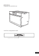
MODEL WFE946SA Touch control electric ceramic hob, programmable touch control electric oven Stainless steel splashback Hob element controls Ceramic glass hob Oven control panel Oven door Storage compartment Stainless steel kick panel Ceramic hob touch controls Control Panel - oven programmable controller ON/OFF FUNCTION FAST HEAT UP Programmable controller Ceramic Hob Triple ring cooking zone Multi-purpose double cooking zone Small cooking zone Small cooking zone DESCRIPTION 8 Medium cooking zo
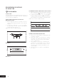
MODEL WVE916SA Programmable touch control electric oven Control Panel - oven programmable controller ON/OFF FUNCTION FAST HEAT UP Programmable controller 9 DESCRIPTION
BEFORE OPERATING YOUR APPLIANCE FOR THE FIRST TIME TIPS & INFORMATION SETTING THE TIME If you have purchased a model fitted with an electronic or programmable timer, you MUST set the time of day before you can operate your appliance. PUSH BUTTON AND TOUCH CONTROL ELECTRONIC CLOCK MODELS WFE912 & WFE914 • After the appliance has been electrically connected “12.00” will be displayed and the “clock” indicator will flash. • To set the time of day, press – or +.
INSTALLING YOUR OVEN ACCESSORIES PRIOR TO INSTALLING ACCESSORIES, REMOVE ALL PACKAGING AND REMOVE PLASTIC FILM FROM EXTERNAL PANELS SIDE RACKS The side racks that come with your oven are fitted in the following manner • Insert the 2 rear pegs into the holes provided • Locate the front peg into the front access hole and push in firmly. CATALYTIC LINERS (ON SELECTED MODELS) Catalytic liners are coated with a specially formulated enamel coating.
INSTALLING YOUR OVEN ACCESSORIES INSTALLING BURNERS AND TRIVETS SHELVES AND TRAYS The shelves are designed so that they have maximum travel but cannot be accidentally pulled right out. The trays are designed in the same way and fit straight into the side racks. • Locate the rear edge of the shelf/tray in between 2 guide rails of the side rack – see diagram. Ensure the same rail positions on both sides of the oven are being engaged. • With the front edge raised, begin to slide the shelf into the oven.
GETTING TO KNOW YOUR GAS COOKTOP USING YOUR GAS HOTPLATES NOTE: Gas controls turn anticlockwise from ‘Off’ and have limited movement. LIGHTING BURNERS Electronic ignition These hobs are fitted with mains powered electronic ignition. When the appliance has been connected and the power is on, depressing any knob will release sparks to all burners. To light a burner, depress the corresponding knob and while continuing to depress knob turn anticlockwise to ‘HI’ position.
GETTING TO KNOW YOUR CERAMIC COOKTOP CERAMIC HOTPLATES MODEL WFE946 The cooktop is made from ceramic glass, a tough, durable material that withstands heating and cooling without breaking. It is strong enough to hold the heaviest utensils. However, it must be remembered that as it is GLASS, it may break. Treat it accordingly! Should you have any questions about the glass in your new appliance, please contact the service centre by dialling 1300 363 640.
GETTING TO KNOW YOUR CERAMIC COOKTOP CERAMIC COOKTOP CONTROLS 2 3 4 5 6 7 8 1 1. 2. 3. 4. 5. 6. 7. 8. 9. 9 ON/OFF WITH POWER INDICATOR LOCK WITH PILOT LIGHT TRIPLE RING COOKING ZONE DISPLAY ZONE INDICATOR HEAT SETTING SELECTION TIMER SETTING SELECTION TIMER DISPLAY MULTIPURPOSE COOKING ZONE The appliance is operated using Touch Control sensor fields. Functions are controlled by touching sensor fields and confirmed by displays and acoustic signals.
USING YOUR CERAMIC COOKTOP SWITCHING THE CERAMIC COOKTOP ON AND OFF CONTROL PANEL DISPLAY Switch on Touch for 2 seconds / Switch off Touch for 2 seconds / none TIPS & INFORMATION After switching on, within approx. 10 seconds a heat setting or a function must be set, otherwise the appliance automatically switches itself off.
USING YOUR CERAMIC COOKTOP The length of time that the automatic warm up function operates depends on the heat setting selected. HEAT SETTING OVERRIDING THE CHILD SAFETY DEVICE The child safety device can be switched off in this way for a single cooking session; it remains activated afterwards. AUTOMATIC WARM UP (MIN:SEC) 0.30 STEP 1. 1.00 2. 1.40 CONTROL PANEL DISPLAY Switch the appliance on Touch for 4 seconds lights up Until the appliance is next switched off, it can be used as normal.
USING YOUR CERAMIC COOKTOP USING THE TIMER FUNCTION SETTING THE TIME OUTCOME AFTER THE TIME HAS LAPSED CONDITION Automatic cut-out a heat setting is set Countdown timer cooking zones not in use acoustic signal 00 flashes Cooking zone switches off acoustic signal 00 flashes STEP CONTROL PANEL DISPLAY 1. Select zone Pilot light for the cooking zone selected flashes 2.
USING YOUR CERAMIC COOKTOP AUTOMATIC SWITCH OFF Cooking surface • If after switching on the cooking surface, a heat setting is not set for a cooking zone within approx. 10 seconds, the cooking surface automatically switches itself off. • If one or more sensor fields are covered by objects (a pan, cloths, etc.) for longer than approx.10 seconds, a signal sounds and the cooking surface switches off automatically.
USING YOUR OVEN UNDERSTANDING YOUR OVEN FUNCTIONS The following lists the oven functions available with the programmable controller (models WFE916, WFE946 & WVE916). Multifunction models (WFE914 & WFE912) have all oven functions except for Fan Assist, Pizza and Fast Heat Up. BASE HEAT Function 4 RAPID HEAT Function 1 Heat comes from the elements surrounding the fans as well as the smaller element above the food. This allows you to preheat your oven 30% quicker than on standard “Bake”.
USING YOUR OVEN DEFROST MAXI GRILL Function 10 Function 7 The “Defrost” function uses low temperature air that is circulated by the fans. You can defrost (thaw) your food before you cook it. You can also use “Defrost” to raise your yeast dough and to dry fruit, vegetables and herbs. FAN GRILL Function 8 “Fan Grill” offers you the benefits of both “Bake” and traditional “Grill” functions. The grill element turns on and off to maintain the set temperature while the fans circulate the heated air.
USING YOUR OVEN OPERATING YOUR OVEN TEMPERATURE AND FUNCTION SELECTORS MODELS WFE912 & WFE914 To set the oven, turn the function selector to the desired cooking function and then turn the temperature selector to the desired temperature. An indicator light above the temperature selector will come on. When the temperature is reached the heating source switches itself off and the indicator light goes out.
USING YOUR OVEN SETTING THE COOKING DURATION 1. Check the clock displays the correct time of day. 2. Select the desired oven function and temperature. The oven indicator light will glow and the heating source will come on. 3. Press “mode“ until the “cook time” indicator I begins flashing. 4. Set the cooking duration you want by using – or +. 5 seconds after the last change, the “cook time” indicator I will stop flashing, and the time of day will be displayed.
USING YOUR OVEN USING YOUR PROGRAMMABLE CONTROLLER TO OPERATE THE OVEN MODELS WFE946 & WVE916 ON/OFF FUNCTION FAST HEAT UP Programmable controller MODEL WFE916 FUNCTION OFF OFF OFF ON/OFF OFF OFF OFF HI HI HI HI HI HI LO LO LO LO LO LO FAST HEAT UP Programmable controller Gas hob burner controls SETTING THE TIME OF DAY After the appliance has been electrically connected the “set clock” symbol will flash on the clock display. 1.
USING YOUR OVEN ON COMPLETION OF COOKING When the set time has elapsed, a signal will sound for 1 minute, the oven will switch off and the remaining time indication “0.00” will appear on the display. 1. To stop the signal, press “+” or “–”. SETTING THE MINUTE MINDER For setting a countdown period. When the period of time has elapsed, an audible signal is sounded. NOTE: This feature has no effect on the oven operation. 1.
COOKING TEST GET TO KNOW YOUR NEW OVEN WITH THIS ‘SIMPLE TEST CAKE’ Although we strive for a perfect performing oven, it’s possible that there will be some variation in colour when baking. Therefore, we suggest this simple, easy and delicious to make Simple Test Cake, it can help you understand your new oven. All ovens do sometimes have hot or cold spots, therefore it is important to judge with your eye as you may require to rotate during baking.
COOKING GUIDE • • • • • • • • • • • • F or best baking results preheat oven for 30 minutes Select the correct shelf location for food being cooked. The grill tray can be used in the oven as a baking dish, except in oven shelf location 1. Make sure dishes will fit into the oven before you switch it on. Keep edges of baking dishes at least 40mm from the side of the oven. This allows free circulation of heat and ensures even cooking. Do not open the oven door more than necessary.
COOKING GUIDE CHOOSING THE BEST OVEN SETTINGS The following table is intended as a guide and experience may show some variation in cooking times necessary to meet individual requirements. We recommend that you preheat your oven for 30 minutes.
COOKING GUIDE ROASTING MEAT 1. Place the meat in the oven and set the temperature between 180°C and 200°C. (It is recommended to wrap your meats in an oven roasting bag or foil to prevent fats and oils from splattering, making it easier to clean your oven.) 2. Use the grill/oven dish and grill insert. Place the meat on the insert. 3. Do not pierce the meat, as this will allow juices to escape. 4.
DEALING WITH COOKING PROBLEMS (SEE ALSO SOLVING PROBLEMS) PROBLEM CAUSES REMEDIES Uneven cooking: • • • • • – Select shelf that puts food in the centre of the oven. – Experiment with other trays or dishes. – Centre trays. – Rotate food during cooking. – Remove grill dish from oven on bake modes. Baked products too brown on top: •O ven not preheated. • Baking tins too large for the recipe. • Baking tins not evenly spaced. I ncorrect shelf position. Oven tray too large.
CLEANING YOUR APPLIANCE • • • WARNING lways make sure that the oven is electrically isolated A before cleaning. This can be done by the functional switch nearby Do not line the bottom of the oven with foil or cookware Do not use steam cleaners STAINLESS STEEL WARNING • The oven door trim, the control panel and the storage compartment are decorated with a special stainless steel that resists finger marks and should only be cleaned with warm water and a mild detergent.
CLEANING YOUR OVEN ACCESSORIES REMOVING THE TRAYS AND SHELVES FROM YOUR APPLIANCE • Slide the dish and grill tray towards you until they reach the front stop. • Tilt them up at the front to clear the side supports, taking care not to spill the contents. • Lift them clear. • Wash the tray and shelves in hot soapy water. • Reverse the above steps to put the grill tray and shelves back again. • Ensure that they are placed between the 2 support wires.
CLEANING YOUR OVEN ACCESSORIES CLEANING YOUR OVEN DOOR • • • • • • • WARNING O NOT use the oven without the inner and middle D door glass fitted. NEVER spray any caustic cleaners on any surface of the door or damage to the surface coatings will result. DO NOT use metal utensils, scrapers, scourers, or abrasive cleaners to clean the glass or any of the door trims. These will damage or scratch the surface coatings and degrade the finish and appearance. DO NOT place glass in dishwasher.
CATALYTIC LINERS (WHERE FITTED) STORAGE COMPARTMENT (SELECTED MODELS) OPERATION The catalytic liners are coated with a specially formulated enamel coating, over a base of regular enamel. This enamel coating has a rough surface which is also porous. During normal cooking, fats and other food spatter is partially absorbed into the surface and then oxidised away. This oxidisation of the fat works best if the oven is set at high temperatures.
SOLVING PROBLEMS FAULTS If there is a problem with the oven and/or grill, please: • Check the points listed below before calling for service. It may be possible to avoid a call by fixing the problem yourself – and so continue cooking. NOTE: We may charge for service even in the guarantee period if your problem is due to the causes listed below.
INSTALLATION OF THE APPLIANCE INSTALLING SPLASHBACK (MODELS WITH HOB ONLY) Fit splashback to rear of hob with three screws provided. CABINET REQUIREMENTS Models WFE912, WFE914, WFE916, & WFE946 are designed to fit into a 900mm wide gap between standard kitchen cabinets. The appliance integrates with the kitchen cabinets by matching the height, depth and kick panel. The cooker may also be installed at the end of a line of benches or with a free space either side.
INSTALLATION OF THE APPLIANCE FLOOR MOUNTED INSTALLATION The floor mounted type installation uses the appliance as supplied, and can be fitted in between cabinets, with cabinets on one side or without adjacent cabinets. There is no clearance requirement to adjacent side cabinets. To ensure cooker stability, the anti-tilt brackets must be installed, and the end of chain attached to the appliance must be placed onto hook attached to the rear wall.
INSTALLATION OF THE APPLIANCE FLOOR MOUNTED INSTALLATION (continued) INSTALLATION OF ANTI-TILT BRACKETS AND HOOK • T he anti-tilt brackets must be secured to the floor at rear of cavity with an appropriate fastener according to dimensions in diagram Hole location for hook installation C L 840 425 425 Measurements are to be adjusted to account for the thickness of any skirting Measurements are tothebe to and account board or tiles coming between backadjusted of the appliance the wall.
INSTALLATION OF THE APPLIANCE SLOT-IN INSTALLATION SLOT IN CONVERSION To convert the appliance for slot in installation the kick panel provided on the appliance is removed and the appliance is mounted on a plinth. This enables a continuous cupboard kick board to be installed, giving a more integrated appearance. There is no clearance requirement between oven and adjacent side cabinets.
INSTALLATION OF THE APPLIANCE SLOT-IN INSTALLATION (continued) INSTALLATION OF ANTI-TILT BRACKETS AND STOPS • The brackets are to be secured to the back wall with appropriate fasteners. • The bottom edge of the the brackets rest on the horizontal support surface. • Two stops are to be screwed to the plinth in locations as shown (stops provided). The stops locate into slots in the base of the appliance to prevent the product from being pulled forward when installed.
BUILT-IN INSTALLATION CABINET CONSTRUCTION FOR BUILT IN OVEN For the best integration within a kitchen, install this appliance in a cupboard that gives a flush fit with the surrounding cupboard fronts. A recess of 20mm is ideal. Alternatively, the oven can be proud mounted. See diagrams below for details. NOTE: Your appliance must be mounted on a flat surface for the full width and depth of the product.
INSTALLATION OF THE APPLIANCE UNDERBENCH INSTALLATION Your underbench oven looks best when the control panel is directly under the benchtop. An upper infill panel may be added if the cooktop placed above the benchtop is too deep. *Refer to cooktop installation instructions for required clearance between cooktop and oven. VERTICAL CABINET INSTALLATION The oven can be built into a vertical cabinet in the same manner as an underbench.
WIRING REQUIREMENTS The cooker MUST be installed in compliance with: • wiring connections in AS/NZS 3000 Wiring Rules • local regulations, municipal building codes and other statutory regulations For New Zealand Only: The cooking range must be connected to the supply by a supply cord fitted with the appropriately rated plug that is compatible with the socket-outlet fitted to the final sub-circuit in the fixed wiring that is intended to supply this cooking range.
ELECTRICAL & GAS CONNECTION LOCATIONS MODELS WFE912, WFE914, WFE916 AND WFE946 168 Gas connection point to regulator Models: WFE912, WFE914, WFE916 806 Electrical cable entry point Models: WFE912, WFE914, WFE916, WFE946 GAS TYPE NATURAL GAS UNIVERSAL LPG WFE912 & WFE914 49.6 MJ/h 40.9 MJ/h WFE916 58.6 MJ/h 47.4 MJ/h Information about the length of run, number of elbows, tees and bends, the available service pressure and the supply requirements. 411 NOTE: AS/NZS5601.
LPG CONVERSION MODELS WFE912, WFE914 & WFE916 This appliance is supplied set up to for Natural Gas usage. A conversion kit is included with the product for Universal LPG usage. The conversion kit contains 6 injectors and 1 LPG sticker. Please follow the procedure below if a conversion to suit UNIVERSAL LPG is required. 1. Remove the hotplate trivets, burner caps and burner crowns to access the hotplate injectors. Replace the factory fitted injectors with the appropriate injectors, as supplied.
TESTING THE OPERATION OF THE GAS COOKER NOTE: You MUST test the cooker after installation, before you hand it over to the customer. You MUST have a manometer and a connecting tube. CHECKING GAS SUPPLY 1. Check the manometer zero point is correct. 2. Connect the manometer to the cooker pressure test point. This is located on the regulator or LPG inlet fitting. 3. Turn on the gas supply and the electricity and try to ignite the gas.
Warranty FOR SALES IN AUSTRALIA AND NEW ZEALAND APPLIANCE: BUILT-IN OVEN, COOKTOP AND UPRIGHT RANGE COOKER This document sets out the terms and conditions of the product warranties for Electrolux Appliances. It is an important document. Please keep it with your proof of purchase documents in a safe place for future reference should you require service for your Appliance. 1.
For more information on all Westinghouse appliances, or for dimension and installation information, call into your retailer, phone or email our customer care team or visit our website: AUSTRALIA phone: 1300 363 640 fax: 1800 350 067 email: customercare@electrolux.com.au web: www.westinghouse.com.au NEW ZEALAND phone: 09 573 2384 fax: 0800 363 600 email: customercare@electrolux.co.nz web: www.westinghouse.co.