
Installation Manual

48
WHL-019 REV. 12.17.14
PART 9 – SHUTDOWN
A. SHUTDOWN PROCEDURE
If the burner is not operating, disconnect the electrical supply.
If the burner is operating, lower the set point value to 70
o
F and wait for the burner to shut off. Continue
to wait for the combustion blower to stop, so all latent combustion gases are purged from the system.
This should take a maximum of 40 to 90 seconds.
B. VACATION PROCEDURE
If there is danger of freezing, change the set point to 70
o
F. DO NOT turn off electrical power. If there is
no danger of freezing, follow “Shutdown Procedure”.
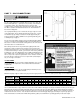
C. FAILURE TO OPERATE
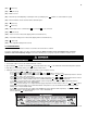
Should the burner fail to light, the control will perform two more ignition trials prior to entering a lockout
state. Note that each subsequent ignition trial will not occur immediately. After a failed ignition trial, the
blower must run for approximately 10 seconds to purge the system. Therefore, a time period of
approximately 40 to 90 seconds will expire between each ignition trial.
If the burner lights during any one of these three ignition trails, normal operation will resume. If the
burner lights, but goes off in about 4 seconds, check the polarity of the wiring. See electrical connection
section.
If the burner does not light after the third ignition trial, the control will enter a lockout state. This lockout
state indicates that a problem exists with the water heater, the controls, or the gas supply. Under such
circumstances, a qualified service technician should be contacted immediately to properly service the
water heater and correct the problem. If a technician is not available, depressing the {S4} button once
will remove the lockout state so additional trials for ignition can be performed. The unit will try to re-light
once every 6 minutes.
PART 10 – TROUBLESHOOTING
A. ERROR CODE
An error code may occur during installation of the heater. This condition may lead to a lock out condition of the controller, which will
need to be manually reset by pressing the {S4} button. These following will help the installer correct the problem before going into a
lock out condition, which will require a manual reset.
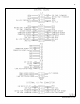
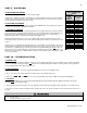
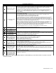
B. HEATER ERROR
1. When an error condition occurs the controller will display an error code on the display module.
2. These error codes and several suggested corrective actions are included in Table 14.
3. In the case of |E00|, |E13|, and |E14| this error, if uncorrected, will go into a fault condition as described in Paragraph C.
C. LOCKOUT
1. When a fault condition occurs the controller will illuminate the red “fault” indication light and display a fault code in the format
(Example: |F00|) on the display module.
2. Note the fault code and refer to Table 15 for an explanation of the fault code along with several suggestions for corrective actions.
3. Press the reset key to clear the fault and resume operation. Be sure to observe the operation of the unit to prevent a recurrence of
the fault.
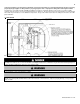
When servicing or replacing any components of this water heater be certain that:
The gas is off.
All electrical power is disconnected.
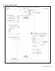
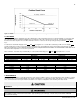
RESISTANCE TABLE FOR
SUPPLY TEMPERATURE
SENSOR
HIGH/LOW
TEMP.
SENSOR
TEMP. (
o
F)
RESISTANCE
(ohms)
32
32550
41
25340
50
19870
59
15700
68
12490
77
10000
86
8059
95
6535
104
5330
113
4372
122
3605
131
2989
140
2490
149
2084
158
1753
167
1481
176
1256
185
1070
194
915
202
786
212
667
Table 13