
Installation Manual

20
WHL-019 REV. 12.17.14
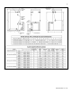
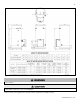
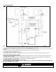
Figure 6 – Water Heater with Air Handler on Side
NOTES:
1. Minimum pipe size should match unit connection size. Upsize pipe accordingly if greater flow is required.
2. A thermal expansion tank suitable for potable water must be sized and installed within this piping system between the backflow preventer and the cold
water inlet.
3. Gas line must be rated to the unit maximum input capacity. Unit must have 10 feet of pipe after gas regulator.
4. All circulators should have an integral flow check.
5. Check with air handler manufacturer for proper sizing.
6. This drawing is meant to demonstrate system piping only. The installer is responsible for all equipment and detailing required by local codes. In
Massachusetts, you must install a vacuum relief valve per 248 CMR. With air handlers, outdoor reset is available with an outdoor sensor. See Part 8,
Section D.
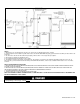
NOTES FOR AIR HANDLER APPLICATION:
1. MASSACHUSETTS STATE PLUMBING CODE REQUIRES A DISTANCE NO GREATER THAN 50 FEET FROM THE WATER HEATER TO THE
FAN COIL IN THE AIR HANDLER.
2. MASSACHUSETTS STATE PLUMBING CODE REQUIRES AN ELECTRONICALLY TIMED CIRCULATOR PUMP TO ACTIVATE EVERY SIX
HOURS FOR 60 SECONDS. THIS CIRCULATOR IS REQUIRED TO BE BRONZE OR STAINLESS.
3. ALL WATER PIPING MUST BE INSULATED.
4. YOU MUST INSTALL A VACUUM RELIEF VALVE PER 248 CMR.
NOTE: THIS DRAWING IS MEANT TO DEMONSTRATE SYSTEM PIPING ONLY. THE INSTALLER IS RESPONSIBLE FOR ALL EQUIPMENT AND
DETAILING REQUIRED BY LOCAL CODES.
An ASSE 1017 thermostatic mixing valve MUST be installed when using outdoor reset. Failure to do so could result in substantial
property damage, serious injury, or death.