USER MANUAL FOR MODELS: WGen2000 WGen3600 WGen3600v 2000 Running Watts 2500 Peak Watts 3600 Running Watts 4650 Peak Watts 3600 Running Watts 4650 Peak Watts Portable Generator Portable Generator Portable Generator
California Proposition 65 Warning California Proposition 65 Warning Certain components in this product and its related accessories contain chemicals known to the state of California to cause cancer, birth defects or other reproductive harm. Wash hands after handling. The engine exhaust from this product contains chemicals known to the state of California to cause cancer, birth defects or other reproductive harm.
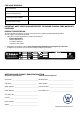
FOR YOUR RECORDS: Date of Purchase: Generator Model Number: Purchased from Store/Dealer: Generator Serial Number: IMPORTANT: KEEP YOUR PURCHASE RECEIPT TO ENSURE TROUBLE-FREE WARRANTY COVERAGE. PRODUCT REGISTRATION To ensure trouble-free warranty coverage, it is important you register your Westinghouse generator. You can register your generator by either: 1. Filling in the product registration form below and mailing to: Product Registration MWE Investments LLC 777 Manor Park Drive Columbus, Ohio 43228 2.
TABLE OF CONTENTS WGEN TECHNICAL SPECIFICATIONS. . . . . . . . . . . . . 2 PRODUCT REGISTRATION. . . . . . . . . . . . . . . . . . . . . . 3 For Your Records: . . . . . . . . . . . . . . . . . . . . . . . . . . . 3 Product Registration . . . . . . . . . . . . . . . . . . . . . . . . 3 Product Registration Form . . . . . . . . . . . . . . . . . . . . 3 SAFETY. . . . . . . . . . . . . . . . . . . . . . . . . . . . . . . . . . . . . . 5 Safety Definitions . . . . . . . . . . . . . . . . . . . . . . . . . . .
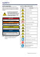
SAFETY SAFETY DEFINITIONS The words DANGER, WARNING, CAUTION and NOTICE are used throughout this manual to highlight important information. Be certain that the meanings of these alerts are known to all who work on or near the equipment. SAFETY SYMBOL DEFINITIONS This safety alert symbol appears with most safety statements. It means attention, become alert, your safety is involved! Please read and abide by the message that follows the safety alerts symbol.
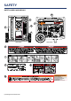
SAFETY GENERAL SAFETY RULES DANGER Never use the generator in a location that is wet or damp. Never expose the generator to rain, snow, water spray or standing water while in use. Protect the generator from all hazardous weather conditions. Moisture or ice can cause a short circuit or other malfunction in the electrical circuit. Never operate the generator in an enclosed area. Engine exhaust contains carbon monoxide. Only operate the generator outside and away from windows, doors and vents.
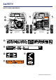
SAFETY SAFETY LABELS AND DECALS 2 1 Par t N0. MWE Investments LLC Columbus Ohio 43228 USA MWE Investments LLC Columbus Ohio 43228 Etats-Unis Numéro de pièc e Designed in Columbus , Ohio USA Co n u à columbus , Ohio,tats-Unis Made in China/ Fabriqu é en Chine CSA Master Contract Number : Numéro de contrat principa l de CSA 3 4 WGen3600 WGen3600 1 2 3 4 Par t N0.
SAFETY SAFETY LABELS AND DECALS 10 6 8 7 5 Sample from WGen5500 9 WGen3600 WGen3600 6 7 268850 268850 8 9 10 Sample from WGen5500 8 | Westinghouse Portable Power
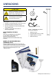
UNPACKING 1 CAUTION 4 Always have assistance when lifting the generator. The generator is heavy; lifting it could cause bodily harm. 2 Avoid cutting on or near staples to prevent personal injury. Tools required – box cutter or similar device. 1. Carefully cut the packing tape on top of the carton. 2. Fold back top flaps to reveal the manual. 3. Remove the Wheel Kit Accessories (WGen3600 only) cardboard box. 4. Carefully cut two sides of the carton to remove the generator.
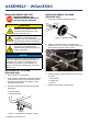
ASSEMBLY - WGen3600 INSTALLING WHEELS AND FEET BEFORE ASSEMBLING THE GENERATOR, REVIEW THE SAFETY SECTION STARTING ON PAGE 5. INSTALLING WHEELS TO FRAME (WGen3600 Only) 1. Insert axle pin through washer and wheel. CAUTION Never lift the generator without assistance. The generator is heavy and lifting without assistance could result in personal injury. Never use the handles as a lifting point to support the entire weight of the generator.
FEATURES WGen3600 2 1 8 3 7 6 9 4 5 1 Engine Control Switch: Allows fuel to flow to 6 Never Flat Wheels (WGen3600 Only): For easy 2 Fuel Cap: Close until clicking sound is heard. 7 Fuel Shut off Valve: Controls the flow of fuel engine and energizes the ignition system. portability to the engine. 3 Control Panel: Contains the circuit breakers 8 Manual Choke: Choke must be set manually by and outlets. adjusting choke lever.
FEATURES 1 2 3 4 WGen3600 1 Fuel Gauge: Indicates fuel level. 2 Spark Plug Boot (Wire): Must be removed when servicing the engine or the spark plug. 3 CARB Canister: Required for models sold into and used in California. 4 Muffler and Spark Arrester: Avoid contact until engine is cooled down. Spark arrestor prevents sparks from exiting the muffler. It must be removed for servicing.
FEATURES CONTROL PANEL FEATURES 1 2 3 4 5 6 WGen3600 3600 Running Watts | 4650 Peak Watts 7 1 Engine Control Switch: Allows fuel to flow to engine and energizes the ignition system. 2 Main Circuit Breaker: The main circuit breaker controls total output of all outlets to protect the generator. 3 120-Volt 30 Amp TT-30R Outlet: Travel Trailer outlet can supply a maximum of 30 amps and 120 volts. 4 120-Volt, 30 Amp Twistlock Outlet (L5-30R ): Outlet can supply 120V output.
OPERATION BEFORE STARTING THE GENERATOR BEFORE STARTING THE GENERATOR, REVIEW SAFETY SECTION STARTING ON PAGE 5. Location Selection – Before starting the generator, avoid exhaust and location hazards by verifying: • You have selected a location to operate the generator that is outdoors and well ventilated. • You have selected a location with a level and solid surface on which to place the generator. • You have selected a location that is at least 6 feet (1.
OPERATION ADDING / CHECKING ENGINE FLUIDS AND FUEL BEFORE ADDING/CHECKING ENGINE FLUIDS AND FUEL, REVIEW SAFETY SECTION STARTING ON PAGE 5. DANGER Filling the fuel tank with gasoline while the generator is running can cause gasoline to leak and come in contact with hot surfaces that can ignite the gasoline.
OPERATION ADDING GASOLINE TO THE FUEL TANK WARNING Never refuel the generator while the engine is running. Always turn the engine off and allow the generator to cool before refueling. Required Gasoline – Only use gasoline that meets the following requirements: • Unleaded gasoline only • Gasoline with maximum 10% ethanol added • Gasoline with an 87 octane rating or higher Filling the Fuel Tank – Follow the steps below to fill the fuel tank: 1. Shut off the generator. 2.
OPERATION MANUALLY STARTING THE GENERATOR 1. Check oil levels (see Adding Engine Oil page 20) 5. Push the engine control switch into the RUN position (see Figure 10 below). 2. Make sure the circuit breakers are properly set (see Figure 7 below). Figure 10 - Engine Control Switch - RUN Figure 7 - Breakers 240/120VMain Circuit Breaker Operating Position 2 240/120V Main Circuit Breaker Tripped Position 3 120V Circuit Breaker Operating Position 4 120V Circuit Breaker Tripped Position 1 6.
OPERATION STOPPING THE GENERATOR Normal Operation During normal operation, use the following steps to stop your generator: 1. Remove any connected loads from the control panel receptacles. 2. Allow the generator to run at “no load” to reduce and stabilize engine and alternator temperatures. 3. Position the engine control switch to STOP or if you plan to store the generator after use, turn the fuel shutoff valve to the OFF position and allow the fuel to be consumed from the carburetor.
MAINTENANCE MAINTENANCE SCHEDULE WARNING CAUTION Failure to perform periodic maintenance or not following maintenance procedures can cause the generator to malfunction and could result in death or serious injury. Avoid skin contact with engine oil or gasoline. Prolonged skin contact with engine oil or gasoline can be harmful. Frequent and prolonged contact with engine oil may cause skin cancer. Take protective measures and wear protective clothing and equipment.
MAINTENANCE ENGINE OIL MAINTENANCE Engine Oil Specification 1. Only use the engine oil specified in Figure 14. 2. Only use 4-stroke/cycle engine oil. NEVER USE 2-STROKE/CYCLE OIL. Synthetic oil is an acceptable substitute for conventional oil. 6. Check oil level: When checking the engine oil, remove the oil fill plug/dipstick and wipe it clean. Thread the oil fill plug/dipstick all the way back in and then remove and check the oil level on the oil fill plug/dipstick.
MAINTENANCE CHANGING ENGINE OIL AIR FILTER MAINTENANCE WARNING 1. Stop the engine. 2. Let engine sit and cool for several minutes (allow crankcase pressure to equalize). 3. Place oil pan (or suitable container) under the oil drain plug (see Figure 17). 4. With a damp rag, thoroughly clean around the oil drain plug. 5. Remove the oil drain plug (see Figure 17). Once removed, place the oil drain plug on a clean surface. Never use gasoline or other flammable solvents to clean the air filter.
MAINTENANCE Cleaning the Air Filter - Continued from Page 21 NOTICE Never dispose of soap cleaning solution used to clean the air filter by dumping the solution into a sewer, on the ground, or into ground water or waterways. Always be environmentally responsible. Follow the guidelines of the EPA or other governmental agencies for proper disposal of hazardous materials. Consult local authorities or reclamation facility. 1. Dispose of used soap cleaning solution properly. 2.
MAINTENANCE CLEANING THE GENERATOR It is important to inspect and clean the generator before every use. Clean All Engine Air Inlet and Outlet Ports – Make sure all engine air inlet and outlet ports are clean of any dirt and debris to ensure the engine does not run hot. Clean All Engine Cooling Fins – Use a damp rag and a brush to loosen and remove all dirt on or around the engine’s cooling fins.
MAINTENANCE 2 1 (Table 2) Standard Valve Lash 3 4 Intake Valve Exhaust Valve Valve Lash 0.0035 ± 0.0043 in (0.09 ± 0.11 mm) 0.0043 ± 0.0051 in (0.11 ± 0.13 mm) Bolt Torque 8-12N.m 8-12N.m 6. If an adjustment is required, hold the adjusting nut and loosen the jam nut. 7. Turn the adjusting nut to obtain the correct valve lash. When the valve lash is correct, hold the adjusting nut and tighten the jam nut to 106 in-lb (12 N•m). 5 8. Recheck the valve lash after tightening the jam nut. 9.
TROUBLESHOOTING Engine will not start or remain running while trying to start. PROBLEM Generator suddenly stops running. Engine runs erratic; does not hold a steady RPM. 1. Fuel shutoff valve is in the OFF position. 1. Move the fuel shut off valve to the ON position (see Figure 8 page 17). 2. Generator is out of gasoline. 2. Add gasoline to the generator (see page 16). 3. Fuel flow is obstructed. 3. Inspect and clean fuel delivery passages. 4. Unit is over choked. 4.
WGen2000 ENGINE VIEW 7.6 180571 M10X80 Stud 2 8 140512 Carburetor Assy 1 No. Part.
WGen2000 EXPLODED VIEW No. Part.
WGen3600 ENGINE VIEW 7.6 180571 M10X80 Stud 2 8 140512 Carburetor Assy 1 No. Part. Description Qty 9 140518 Fuel Hose 1 1 180556 Ball Bearing 2 10 140508 Hose Clamp 1 2 180541 Oil Seal 2 11 180549 Govenor Arm 1 3 180543 Drain Plug 2 12 100548 M6 Nut 3 4 180544 Drain Plug Seal 2 13 180545 Gasket 1 5 180546 Crankcase Cover 1 14 110503 M8X30 6 6 170502 Hose Clip 1 15 180547 1 7 180548 Cylinder Head Assy 1 Cylinder Head Gasket 7.
WGen3600 EXPLODED VIEW No. Part. Description Qty 1 100536 Frame 1 2 105560 Damper 2 3 100559 Damper 2 4 100520 M8 Nut 4 5 180524 M8 Nut 6 6 150519 Hose 1 7 180569 Bracket 1 8 120505 M6X12 15 9 110520 Bracket 1 10 180565 Engine Assy 1 11 130519 Control Panel Assy 1 11.1 130509 Circuit Breaker 1P30A 1 11.2 130502 Start Switch 1 11.3 130510 L5-30 Receptacle 1 11.4 130511 TT-30 Receptacle 1 11.5 130507 Circuit Breaker 1P20A 1 11.
WGen3600v ENGINE VIEW 7.6 180571 M10X80 Stud 2 8 140512 Carburetor Assy 1 No. Part. Description Qty 9 140518 Fuel Hose 1 1 180556 Ball Bearing 2 10 140508 Hose Clamp 1 2 180541 Oil Seal 2 11 180549 Govenor Arm 1 3 180543 Drain Plug 2 12 100548 M6 Nut 3 4 180544 Drain Plug Seal 2 13 180545 Gasket 1 5 180546 Crankcase Cover 1 14 110503 M8X30 6 6 170502 Hose Clip 1 15 180547 1 7 180548 Cylinder Head Assy 1 Cylinder Head Gasket 7.
WGen3600v EXPLODED VIEW No. Part. Description Qty 1 100560 Frame 1 2 105560 Damper 2 3 100559 Damper 2 4 100520 M8 Nut 4 5 180524 M8 Nut 4 6 150519 Hose 1 7 180569 Bracket 1 8 120505 M6X12 15 9 110520 Bracket 1 10 180565 Engine Assy 1 11 130519 Control Panel Assy 1 11.1 130509 Circuit Breaker 1P30A 1 11.2 130502 Start Switch 1 11.3 130510 L5-30 Receptacle 1 11.4 130511 TT-30 Receptacle 1 11.5 130524 Circuit Breaker 1P20A 1 11.
WGen3600/WGen3600v SCHEMATIC 32 | Westinghouse Portable Power
WGen2000 SCHEMATIC Westinghouse Portable Power | 33
Maintenance Notes 34 | Westinghouse Portable Power
Maintenance Notes Westinghouse Portable Power | 35
Version 7.11.