USER MANUAL WGen5500 Portable Generator 5500 Running Watts | 6850 Peak Watts
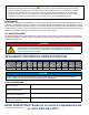
WARNING Operating, servicing and maintaining this equipment can expose you to chemicals i ncluding engine exhaust, carbon monoxide, phthalates, and lead, which are known to the State of California to cause cancer and birth defects or other reproductive harm. To minimize exposure, avoid breathing exhaust, do not idle the engine except as necessary, service your equipment in a well-ventilated area and wear gloves or wash your hands frequently when servicing your equipment.
IMPORTANT: KEEP YOUR PURCHASE RECEIPT TO ENSURE TROUBLE-FREE WARRANTY COVERAGE. PRODUCT REGISTRATION To ensure trouble-free warranty coverage, it is important you register your Westinghouse generator. You can register your generator by either: 1. Filling in the product registration form below and mailing to: Product Registration MWE Investments LLC 777 Manor Park Drive Columbus, Ohio 43228 2. Registering your product Online at wpowereq.
TABLE OF CONTENTS WGEN5500 TECHNICAL SPECIFICATIONS. . . . . . . . . 2 PRODUCT REGISTRATION. . . . . . . . . . . . . . . . . . . . . . 3 Locate Serial Number . . . . . . . . . . . . . . . . . . . . . . . . 3 Product Registration . . . . . . . . . . . . . . . . . . . . . . . . 3 Product Registration Form . . . . . . . . . . . . . . . . . . . . 3 SAFETY. . . . . . . . . . . . . . . . . . . . . . . . . . . . . . . . . . . . . . 5 Safety Definitions . . . . . . . . . . . . . . . . . . . . . . . . . . .
SAFETY SAFETY DEFINITIONS The words DANGER, WARNING, CAUTION and NOTICE are used throughout this manual to highlight important information. Be certain that the meanings of these alerts are known to all who work on or near the equipment. This safety alert symbol appears with most safety statements. It means attention, become alert, your safety is involved! Please read and abide by the message that follows the safety alerts symbol.
SAFETY GENERAL SAFETY RULES DANGER Never use the generator in a location that is wet or damp. Never expose the generator to rain, snow, water spray or standing water while in use. Protect the generator from all hazardous weather conditions. Moisture or ice can cause a short circuit or other malfunction in the electrical circuit. Never operate the generator in an enclosed area. Engine exhaust contains carbon monoxide. Only operate the generator outside and away from windows, doors and vents.
SAFETY SAFETY LABELS AND DECALS 5 2 1 5 3 4 1 2 4 Par t N0.
SAFETY SAFETY LABELS AND DECALS 6 7 8 9 6 7 8 10 8 | Westinghouse Portable Power 9 10 5
UNPACKING 1 CAUTION 4 Always have assistance when lifting the generator. The generator is heavy; lifting it could cause bodily harm. 2 Avoid cutting on or near staples to prevent personal injury. Tools required – box cutter or similar device. 1. Carefully cut the packing tape on top of the carton. 2. Fold back top flaps to reveal the manual. 3. Remove the Wheel Kit Accessories cardboard box. 4. Carefully cut two sides of the carton to remove the generator.
ASSEMBLY INSTALLING WHEELS AND FEET BEFORE ASSEMBLING THE GENERATOR, REVIEW THE SAFETY SECTION STARTING ON PAGE 5. INSTALLING WHEELS TO FRAME 1. Insert axle pin through washer and wheel. CAUTION Never lift the generator without assistance. The generator is heavy and lifting without assistance could result in personal injury. Never use the handles as a lifting point to support the entire weight of the generator.
FEATURES 2 1 7 3 8 9 4 6 5 1 Engine Control Switch: Allows fuel to flow to engine and energizes the ignition system. 2 Fuel Cap: Close until clicking sound is heard. 6 Never Flat Wheels: For easy portability 7 Fuel Shut off Valve: Controls the flow of fuel to the engine. 3 Control Panel: Contains the circuit breakers 8 Manual Choke: Choke must be set manually by 4 Oil Fill Plug/Dipstick: Must be removed to add 9 Single Piece Handle: Includes rubber grip. Allows and outlets. and check oil.
FEATURES 12 13 16 14 15 12 Fuel Gauge: Indicates fuel level. 13 Spark Plug Boot (Wire): Must be removed when servicing the engine or the spark plug. 14 CARB Canister: Required for models sold into and used in California. 15 Muffler and Spark Arrester: Avoid contact until engine is cooled down. Spark arrestor prevents sparks from exiting the muffler. It must be removed for servicing. 16 Alternator Cover: Gain access to alternator wiring.
FEATURES CONTROL PANEL FEATURES 1 2 3 4 5 6 7 Figure 4 - Control Panel Features 1 Engine Control Switch: Allows fuel to flow to engine and energizes the ignition system. 2 Data Center: The VFT Meter is an LED display that will rotate through volts, frequency, and lifetime run hours. You can press the MODE button to cycle through the different displays. The frequency and voltage can vary +/- 5% and still be within tolerance.
OPERATION BEFORE STARTING THE GENERATOR BEFORE STARTING THE GENERATOR, REVIEW SAFETY SECTION STARTING ON PAGE 5. Location Selection – Before starting the generator, avoid exhaust and location hazards by verifying: • You have selected a location to operate the generator that is outdoors and well ventilated. • You have selected a location with a level and solid surface on which to place the generator. • You have selected a location that is at least 15 feet (4.
OPERATION POWERCORD Using Extension Cords Westinghouse Portable Power assumes no responsibility for the content within this table. The use of this table is the responsibility of the user only. This table is intended for reference only. The results produced by using this table are not guaranteed to be correct or applicable in all situations as the type and construction of cords are highly variable.
OPERATION CONNECTING THE GENERATOR TO A BUILDING ELECTRICAL SYSTEM It is recommended to use a manual transfer switch when connecting directly to a buildings electrical system. Connecting a portable generator to a buildings electrical system must be made in strict compliance with all national and local electrical codes and laws, and be completed by a qualified electrician. TRANSFER SWITCH CONNECTIONS The Westinghouse generator is wired with the neutral bonded to ground.
OPERATION ADDING GASOLINE TO THE FUEL TANK WARNING Never refuel the generator while the engine is running. Always turn the engine off and allow the generator to cool before refueling. Required Gasoline – Only use gasoline that meets the following requirements: • Unleaded gasoline only • Gasoline with maximum 10% ethanol added • Gasoline with an 87 octane rating or higher Filling the Fuel Tank – Follow the steps below to fill the fuel tank: 1. Shut off the generator. 2.
OPERATION POWER OUTPUT AND DEMAND The generator should not be run completely unloaded for extended periods otherwise the engine may be damaged. It is recommended that the generator should always be operated with at least one-third of its rated 120-Volt AC power output. 120-Volt AC devices have two different electric power demands that must be taken into consideration, namely the running power and the starting/ peak power. Both are measured in Watts (typically abbreviated as “W”).
OPERATION 5. Push the engine control switch into the RUN position (see Figure 11). STOPPING THE GENERATOR Normal Operation During normal operation, use the following steps to stop your generator: 1. Remove any connected loads from the control panel receptacles. 2. Allow the generator to run at “no load” to reduce and stabilize engine and alternator temperatures. Figure 11 - Engine Control Switch - RUN 3. Position the engine control switch to STOP. 6.
MAINTENANCE BEFORE PERFORMING MAINTENANCE ON THE GENERATOR, REVIEW THE SAFETY SECTION STARTING ON PAGE 5, AS WELL AS THE FOLLOWING SAFETY MESSAGES. WARNING Avoid accidentally starting the generator during maintenance by removing the spark plug boot from the spark plug. For electric start generators, also disconnect the battery cables from the battery (disconnect the black negative (-) cable first) and place the cables away from the battery posts to avoid arcing.
MAINTENANCE TABLE 2: MAINTENANCE SCHEDULE - AUTHORIZED WESTINGHOUSE SERVICE DEALER PERFORMED Before Every Use After First 20 Hours or First Month of Use Valve Clearance - - - - Check/Adjust Fuel Filter - - - Check/Clean - Idle Speed - - - - Check/Adjust Maintenance Item CLEANING THE SPARK ARRESTOR WARNING Hot Surfaces. When operating machine, do not touch hot surfaces. Keep machine away from combustibles during use. Hot surfaces could result in severe burns or fire.
MAINTENANCE ENGINE OIL MAINTENANCE Engine Oil Specification 1. Only use the engine oil specified in Figure 17. 2. Only use 4-stroke/cycle engine oil. NEVER USE 2-STROKE/CYCLE OIL. Synthetic oil is an acceptable substitute for conventional oil. 6. Check oil level: When checking the engine oil, remove the oil fill plug/dipstick and wipe it clean. Thread the oil fill plug/dipstick all the way back in and then remove and check the oil level on the oil fill plug/ dipstick.
MAINTENANCE CHANGING ENGINE OIL 1. Always operate or maintain the generator on a flat surface. 2. Stop the engine. 3. Let engine sit and cool for several minutes (allow crankcase pressure to equalize). 4. Place oil pan (or suitable container) under the oil drain plug (see Figure 20). 5. With a damp rag, thoroughly clean around the oil drain plug. 6. Remove the oil drain plug (see Figure 20). Once removed, place the oil drain plug on a clean surface.
MAINTENANCE Cleaning the Air Filter - Continued from Page 23 NOTICE Never dispose of soap cleaning solution used to clean the air filter by dumping the solution into a sewer, on the ground, or into ground water or waterways. Always be environmentally responsible. Follow the guidelines of the EPA or other governmental agencies for proper disposal of hazardous materials. Consult local authorities or reclamation facility. Figure 23 - Remove Spark Plug Boot 7. Dispose of used soap cleaning solution properly.
MAINTENANCE CHECKING AND ADJUSTING VALVE LASH CAUTION Checking and adjusting valve lash must be done when the engine is cold. 1. Remove the rocker arm cover and carefully remove the gasket. If the gasket is torn or damaged, it must be replaced. 2. Remove the spark plug so the engine can be rotated more easily. 3. Rotate the engine to top dead center (TDC) of the compression stroke. Looking through the spark plug hole, the piston should be at the top. 4.
MAINTENANCE STORING GENERATOR 4. With the fuel shut off valve open, start the engine and allow the generator to run until all the remaining gasoline in the fuel lines and carburetor is consumed and the engine shuts off. WARNING Never store a generator with fuel in the tank indoors or in a poorly ventilated area where the fumes can come in contact with an ignition source such as a: 1) pilot light of a stove, water heater, clothes dryer or any other gas appliance; or 2) spark from an electric appliance. 5.
TROUBLESHOOTING PROBLEM Engine will not start or remain running while trying to start. Generator suddenly stops running. Engine runs erratic; does not hold a steady RPM. POTENTIAL CAUSE SOLUTION 1. Fuel shutoff valve is in the OFF position. 1. Move the fuel shut off valve to the ON position. 2. Generator is out of gasoline. 2. Add gasoline to the generator. 3. Fuel flow is obstructed. 3. Inspect and clean fuel delivery passages. 4. Starting battery may have insufficient charge 4.
WGen5500 EXPLODED VIEW Westinghouse Generator Accessories (call to order) 210004 GENERATOR COVER 210003 WGC25 25’ POWER CORD 210052 30A 6 BREAKER TRANSFER SWITCH KIT - MODEL WHMTS30 210075 25’ Cord 30AMP Transfer Switch 210076 50A 6 BREAKER TRANSFER SWITCH KIT - MODEL WHMTS50 210051 25’ Cord 50AMP Transfer Switch 28 | Westinghouse Portable Power
WGen5500 EXPLODED VIEW PART NO. No. Part. Description No. Part.
WGen5500 ENGINE VIEW No. 30 | Westinghouse Portable Power Part.
WGen5500 ENGINE VIEW PART NO. 12 180604 DOWEL PIN, CASE COVER 34 180810 ROD, PUSH 13 190407 PISTON 35 180520 SHROUD 14 190406 PISTON RING SET 36 120505 BOLT M6X12 15 190405 ROD ASSEMBLY.
WGen5500 SCHEMATIC 32 | Westinghouse Portable Power
WGen5500 Specifications Gasoline Running Watts Gasoline Peak Watts Running Amps 5500 Choke Location Above Air Filter (1) 120/240V 30A (L14-30R), (2) Duplex 120V 20A GFCI (5-20R) 6850 23 amps Peak Amps 28 amps AC Voltage 120/240 Volts AC Outlets Ground Neutral Bonded AC Frequency 60 Hz Covered Outlets Yes Engine Horse Power (HP) 13 HP Transfer Switch Ready Yes Total Harmonic Distortion (THD) <23% Westinghouse Portable Transfer Switch Ready (ST Switch) No GFCI Outlets Yes VFT Data Cen
| Westinghouse Portable Power Version 07.23.