USER MANUAL REMOTE START WGen9500 Portable Generator 9500 Running Watts | 12500 Peak Watts
WARNING Operating, servicing and maintaining this equipment can expose you to chemicals i ncluding engine exhaust, carbon monoxide, phosphates, and lead, which are known to the State of California to cause cancer and birth defects or other reproductive harm. To minimize exposure, avoid breathing exhaust, do not idle the engine except as necessary, service your equipment in a well-ventilated area and wear gloves or wash your hands frequently when servicing your equipment.
IMPORTANT: KEEP YOUR PURCHASE RECEIPT TO ENSURE TROUBLE-FREE WARRANTY COVERAGE. PRODUCT REGISTRATION To ensure trouble-free warranty coverage, it is important you register your Westinghouse generator. You can register your generator by either: 1. Filling in the product registration form below and mailing to: Product Registration MWE Investments LLC 777 Manor Park Drive Columbus, Ohio 43228 2. Registering your product Online at wpowereq.
TABLE OF CONTENTS WGEN9500 TECHNICAL SPECIFICATIONS. . . . . . . . . 2 PRODUCT REGISTRATION. . . . . . . . . . . . . . . . . . . . . . 3 Locate Serial Number . . . . . . . . . . . . . . . . . . . . . . . . 3 Product Registration . . . . . . . . . . . . . . . . . . . . . . . . 3 Product Registration Form . . . . . . . . . . . . . . . . . . . . 3 SAFETY. . . . . . . . . . . . . . . . . . . . . . . . . . . . . . . . . . . . . . 5 Safety Definitions . . . . . . . . . . . . . . . . . . . . . . . . . . .
SAFETY SAFETY DEFINITIONS The words DANGER, WARNING, CAUTION and NOTICE are used throughout this manual to highlight important information. Be certain that the meanings of these alerts are known to all who work on or near the equipment. This safety alert symbol appears with most safety statements. It means attention, become alert, your safety is involved! Please read and abide by the message that follows the safety alerts symbol.
SAFETY GENERAL SAFETY RULES DANGER Never use the generator in a location that is wet or damp. Never expose the generator to rain, snow, water spray or standing water while in use. Protect the generator from all hazardous weather conditions. Moisture or ice can cause a short circuit or other malfunction in the electrical circuit. Never operate the generator in an enclosed area. Engine exhaust contains carbon monoxide. Only operate the generator outside and away from windows, doors and vents.
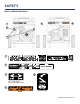
SAFETY SAFETY LABELS AND DECALS 5 2 1 5 3 4 1 2 4 Par t N0.
SAFETY SAFETY LABELS AND DECALS 6 7 8 9 6 7 8 10 8 | Westinghouse Portable Power 9 10 5
UNPACKING 1 CAUTION 4 Always have assistance when lifting the generator. The generator is heavy; lifting it could cause bodily harm. 2 Avoid cutting on or near staples to prevent personal injury. Tools required – box cutter or similar device. 1. Carefully cut the packing tape on top of the carton. 2. Remove the Wheel Kit Accessories cardboard box. 3. Carefully cut two sides of the carton to remove the generator.
ASSEMBLY INSTALLING WHEELS AND FEET BEFORE ASSEMBLING THE GENERATOR, REVIEW THE SAFETY SECTION STARTING ON PAGE 5. INSTALLING WHEELS TO FRAME 1. Insert axle pin through washer and wheel. CAUTION Never lift the generator without assistance. The generator is heavy and lifting without assistance could result in personal injury. Never use the handles as a lifting point to support the entire weight of the generator.
ASSEMBLY CONNECTING THE BATTERY WARNING To avoid electrics hock: • ALWAYS connect the positive (+) battery cable (red boot) first when connecting battery cables. • ALWAYS disconnect the negative (-) battery cable (black boot) first when disconnecting battery cables. • NEVER connect the negative (-) battery cable (black boot) to the positive (+) post on the battery. • NEVER connect the positive (+) battery cable (red boot) to the negative (-) post on the battery.
FEATURES 3 1 2 4 6 11 7 12 8 5 10 1 Push Button Electric Start: Starts and stops the engine. 2 Engine Control Switch/Battery Disconnect: Allows fuel to flow to engine and energizes the ignition system. Also, disconnects battery power when in “Stop” position. 3 Fuel Cap: Close until clicking sound is heard. 4 Control Panel: Contains the circuit breakers and outlets. 5 Battery: Included for electric start models. 6 Oil Fill Plug/Dipstick: Must be removed to add and check oil.
FEATURES 13 14 18 17 15 16 13 Fuel Gauge: Indicates fuel level. 14 Spark Plug Boot (Wire): Must be removed when servicing the engine or the spark plug. 15 CARB Canister: Required for models sold into and used in California. 16 Muffler and Spark Arrester: Avoid contact until engine is cooled down. Spark arrestor prevents sparks from exiting the muffler. It must be removed for servicing. 17 Alternator Cover: Gain access to alternator wiring.
FEATURES CONTROL PANEL FEATURES 1 2 9 3 4 10 5 11 1 Push Button Electric Start: • Push for 1 second to automatically start the engine. • Push again to stop the engine. 2 Engine Control Switch/Battery Disconnect: Switch to “Stop” to stop the engine. When in “Stop” position it prevents the unit from drawing power from the battery. Switch to “Run” before starting engine. 3 Smart Switch Outlet: Connects the Westinghouse ST Switch (sold separately) to the control panel.
OPERATION BEFORE STARTING THE GENERATOR BEFORE STARTING THE GENERATOR, REVIEW SAFETY SECTION STARTING ON PAGE 5. Location Selection – Before starting the generator, avoid exhaust and location hazards by verifying: • You have selected a location to operate the generator that is outdoors and well ventilated. • You have selected a location with a level and solid surface on which to place the generator. • You have selected a location that is at least 15 feet (4.
OPERATION POWER CORD Using Extension Cords Westinghouse Portable Power assumes no responsibility for the content within this table. The use of this table is the responsibility of the user only. This table is intended for reference only. The results produced by using this table are not guaranteed to be correct or applicable in all situations as the type and construction of cords are highly variable.
OPERATION CONNECTING THE GENERATOR TO A BUILDING ELECTRICAL SYSTEM It is recommended to use a manual transfer switch when connecting directly to a buildings electrical system. Connecting a portable generator to a buildings electrical system must be made in strict compliance with all national and local electrical codes and laws, and be completed by a qualified electrician.
OPERATION ADDING GASOLINE TO THE FUEL TANK WARNING Never refuel the generator while the engine is running. Always turn the engine off and allow the generator to cool before refueling. Required Gasoline – Only use gasoline that meets the following requirements: • Unleaded gasoline only • Gasoline with maximum 10% ethanol added • Gasoline with an 87 octane rating or higher Filling the Fuel Tank – Follow the steps below to fill the fuel tank: 1. Shut off the generator. 2.
OPERATION PROGRAMMING THE GENERATOR FOR REMOTE START NOTICE The key fob included with the generator should come already paired with the unit. If it does not you can follow the directions below to reconnect. If your unit was shipped without a key fob please contact our customer support team. WARNING Always make sure the area around the generator is clear of bystanders before using the remote start to start the generator.
OPERATION ELECTRIC START Be sure to check oil levels before starting. If it is the first time starting make sure to add oil (see Adding Engine Oil). 5. Push the engine control switch into the RUN position (see Figure 10). 1. Make sure nothing is plugged into power outlets 2. Verify the battery is properly installed and both battery cables are attached (see Connecting the Battery). 3. Make sure the circuit breakers are properly set (see Figure 8). Figure 10 - Engine Control Switch - RUN 6.
OPERATION MANUALLY STARTING THE GENERATOR Be sure to check oil levels before starting. If it is the first time starting make sure to add oil (see Adding Engine Oil). 1. Make sure nothing is plugged into power outlets 2. Make sure the circuit breakers are properly set (see Figure 8). 3. Move the fuel valve to the ON position (see Figure 9). 4. Push the engine control switch into the RUN position (see Figure 10). 5. Manually set the choke: a.
MAINTENANCE BEFORE PERFORMING MAINTENANCE ON THE GENERATOR, REVIEW THE SAFETY SECTION STARTING ON PAGE 5, AS WELL AS THE FOLLOWING SAFETY MESSAGES. WARNING Avoid accidentally starting the generator during maintenance by removing the spark plug boot from the spark plug. For electric start generators, also disconnect the battery cables from the battery (disconnect the black negative (-) cable first) and place the cables away from the battery posts to avoid arcing.
MAINTENANCE TABLE 2: MAINTENANCE SCHEDULE - AUTHORIZED WESTINGHOUSE SERVICE DEALER PERFORMED Before Every Use After First 20 Hours or First Month of Use Valve Clearance - - - - Check/Adjust Fuel Filter - - - Check/Clean - Idle Speed - - - - Check/Adjust Maintenance Item CLEANING THE SPARK ARRESTOR WARNING Hot Surfaces. When operating machine, do not touch hot surfaces. Keep machine away from combustibles during use. Hot surfaces could result in severe burns or fire.
MAINTENANCE ENGINE OIL MAINTENANCE Engine Oil Specification 1. Only use the engine oil specified in Figure 17. 2. Only use 4-stroke/cycle engine oil. NEVER USE 2-STROKE/CYCLE OIL. Synthetic oil is an acceptable substitute for conventional oil. 6. Check oil level: When checking the engine oil, remove the oil fill plug/dipstick and wipe it clean. Thread the oil fill plug/dipstick all the way back in and then remove and check the oil level on the oil fill plug/ dipstick.
MAINTENANCE CHANGING ENGINE OIL 1. Always operate or maintain the generator on a flat surface. 2. Stop the engine. 3. Let engine sit and cool for several minutes (allow crankcase pressure to equalize). 4. Place oil pan (or suitable container) under the oil drain plug (see Figure 20). 5. With a damp rag, thoroughly clean around the oil drain plug. 6. Remove the oil drain plug (see Figure 20). Once removed, place the oil drain plug on a clean surface.
MAINTENANCE Cleaning the Air Filter - Continued NOTICE Never dispose of soap cleaning solution used to clean the air filter by dumping the solution into a sewer, on the ground, or into ground water or waterways. Always be environmentally responsible. Follow the guidelines of the EPA or other governmental agencies for proper disposal of hazardous materials. Consult local authorities or reclamation facility. Figure 23 - Remove Spark Plug Boot 7. Dispose of used soap cleaning solution properly. 4.
MAINTENANCE CHECKING AND ADJUSTING VALVE LASH CAUTION Checking and adjusting valve lash must be done when the engine is cold. 1. Remove the rocker arm cover and carefully remove the gasket. If the gasket is torn or damaged, it must be replaced. 2. Remove the spark plug so the engine can be rotated more easily. 3. Rotate the engine to top dead center (TDC) of the compression stroke. Looking through the spark plug hole, the piston should be at the top. 4.
MAINTENANCE BATTERY REPLACEMENT 1. Remove the spark plug wire from spark plug. 2. Loosen and remove the bolt on the battery hold down plate and swing the plate out. 3. Tip the battery forward slightly to access battery cables. 4. Disconnect the black negative (-) battery cable from the battery first. 5. Disconnect the red positive (+) battery cable second and remove the battery. NOTICE Dispose of the used battery properly according to the guidelines established by your local or state government. 6.
TROUBLESHOOTING WARNING Before attempting to service or troubleshoot the generator, the owner or service technician must first read the owner’s manual and understand and follow all safety instructions. Failure to follow all instructions may result in conditions that can lead to voiding of the EPA certification or product warranty, serious personal injury, property damage or even death. PROBLEM POTENTIAL CAUSE SOLUTION 1. Circuit breakers are tripped. 1.
TROUBLESHOOTING PROBLEM Generator suddenly stops running. Engine runs erratic; does not hold a steady RPM. 30 | Westinghouse Portable Power POTENTIAL CAUSE SOLUTION 1. Generator is out of fuel. 1. Check fuel level. Add fuel if necessary. 2. The low oil shut down switch has stopped the engine. 2. Check oil level and add oil if necessary. 3. Too much load 3. Restart the generator and reduce the load. 4. If trying 1-3 above does not solve the problem,the cause might be a fault in the generator. 4.
WGen9500 SCHEMATIC Westinghouse Portable Power | 31
68 WGen9500 EXPLODED VIEW Westinghouse Generator Accessories (call to order) 210004 GENERATOR COVER 210003 WGC25 25’ POWER CORD 210052 30A 6 BREAKER TRANSFER SWITCH KIT - MODEL WHMTS30 210075 25’ CORD 30AMP TRANSFER SWITCH 210076 50A 6 BREAKER TRANSFER SWITCH KIT - MODEL WHMTS50 210051 25’ CORD 50AMP TRANSFER SWITCH 130573 25’ L14-50R EXTENSION CORD (120/240-V, 50A OUTLET) 32 | Westinghouse Portable Power
WGen9500 EXPLODED VIEW PART NO. No. Part. DESCRIPTION No. Part.
WGen9500 ENGINE VIEW NO. 34 | Westinghouse Portable Power PART.
WGen9500 ENGINE VIEW PART NO. NO. PART. DESCRIPTION NO. PART. DESCRIPTION 12 180604 DOWEL PIN, CASECOVER 53 180810 ROD, PUSH 13 180787 PISTON 54 180811 SHROUD 14 180788 SCRAPER RING SET, PISTON 55 120505 BOLT M6X12 15 180789 ROD ASSEMBLY.
WGen9500 Specifications Gasoline Running Watts Gasoline Peak Watts Running Amps Peak Amps 9500 Fuel Tank Material 12500 Fuel Tank Capacity (Gallons/Liters) 79A @ 120V 39.5A @ 240V 104A @ 120V 52A @ 240V AC Voltage 120/240 Volts DC Voltage 5 Volts AC Frequency 60 Hz Parallel Capable 13.5 HP Total Harmonic Distortion (THD) <23% 6.6 gal. (25 L) Run Time at %25 Load (hrs.) 17.5 hrs. Run Time at %50 Load (hrs.) 12 hrs.
Service Hotline: (855) 944-3571 777 Manor Park Drive Columbus, OH 43228 TM & © 2019 Westinghouse Electric Corporation © 2019 MWE Investments, LLC. All Rights Reserved. Version 10.25.