
Instructions / Assembly


33
WHL-001 REV. 9.3.14
3. INDOOR COMBUSTION AIR INSTALLATION IN CONFINED OR UNCONFINED SPACE
This heater requires fresh, uncontaminated air for safe operation and must be installed in a mechanical room where there is adequate
combustion and ventilating air. NOTE: To prevent combustion air contamination, see Table 1 – Contaminant Table on page 12.
Combustion air from the indoor space can be used if the space has adequate area or when air is provided through a duct or louver to
supply sufficient combustion air based on the water heater input. Never obstruct the supply of combustion air to the water heater.
If the water heater is installed in areas where indoor air is contaminated (see Figure 13) it is imperative that the water heater be
installed as direct vent so that all combustion air is taken directly from the outdoors into the water heater intake connection.
Unconfined space is space with volume greater than 50 cubic feet per 1,000 Btu/hour (4.8 cubic meters per kW) of the total input
rating of all fuel-burning appliances installed in that space. Rooms connected directly to this space, through openings not furnished with
doors, are considered part of the space.
Confined space is space with volume less than 50 cubic feet per 1,000 Btu/hour (4.8 cubic meters per kW) of the total input rating of
all fuel-burning appliances installed in that space. Rooms connected directly to this space, through openings not furnished with doors,
are considered part of the space.
When drawing combustion air from inside a conventionally constructed building to a confined space, such space should be provided
with two permanent openings: one located 6” (15 cm) below the space ceiling, the other 6” (15cm) above the space floor. Each opening
should have a free area of one square inch per 1,000 Btu/hr (22cm
2
/kW) of the total input of all appliances in the space, but not less
than 100 square inches (645cm
2
).
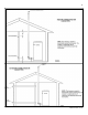
If the confined space is within a building of tight construction, air for
combustion must be obtained from the outdoors as outlined in the Venting
section of this manual. See Figure 14.
Figure 13 – LP-325-X