
Instructions / Assembly


25
WHL-001 REV. 9.3.14
You must not use “B” vent in an exhaust application. “B” vent is for intake applications ONLY. Using “B” vent in an exhaust application
will result in serious injury or death.
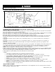
D. EXHAUST VENT AND INTAKE PIPE LOCATION
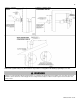
Figure 7 – ANSI Z223.1 / NFPA 54 for US and CAN/CSA B149.1 for Canada – Exit Terminals for Direct-Vent Venting Systems
DETERMINE EXHAUST VENT AND INTAKE PIPE LOCATION – FIGURE 7 NOTES:
INSTALLATIONS IN THE UNITED STATES
A. Provide a minimum of 1 foot clearance from the bottom of the exhaust vent and intake pipe above the expected snow accumulation
level. Snow removal may be necessary to maintain clearance.
B. Provide a minimum of 1 foot distance from exhaust vent termination to any door, operable window, or gravity intake into any building.
C. Provide a minimum of 1 foot distance from exhaust vent termination to any permanently closed door or window.
D. Provide a minimum of 4 feet vertical clearance from the exhaust vent to all roof overhangs.
E. Locating exhaust vent termination near roof overhangs will result in the formation of icicles in freezing weather, and could result in
blockage of the exhaust vent. To prevent icicles from forming, maintain 4 feet vertical clearance from the exhaust vent to all roof
overhangs.
F. Provide 4 feet clearance from the outside corner of vertical walls, chimneys, etc., as well as horizontal corners created by roof
overhangs.
G. Provide 6 feet clearance from the inside corner of vertical walls, chimneys, etc., as well as horizontal corners created by roof
overhangs.
H. Provide 4 feet clearance from center line within a height of 15 feet above electrical meters, gas meters, gas regulators, relief
equipment, exhaust fans and inlets.
I. Provide 4 feet horizontal clearance from electrical meters, gas meters, gas regulators, relief equipment, exhaust fans and inlets. In no
case shall the exit terminal be above or below the aforementioned equipment unless the 4 foot horizontal distance is maintained.
J. This water heater vent system shall terminate at least 3 feet (0.9 m) above any forced air intake located within 10 ft (3 m).
NOTE: This does not apply to the combustion air intake of a direct-vent appliance.
K. When venting with a two pipe system, maximum distance between exhaust vent and intake pipe is 6 feet (1.8 m). Minimum distance
between exhaust vent and intake pipe on single direct vented appliance is 10” (0.255 m) center-to-center. Minimum distance between
exhaust vents and intake pipes on multiple water heaters is 10” (0.255 m) center-to-center.
L. When adjacent to a public walkway, locate exit terminal at least 7 feet above grade.
In addition:
Total length of vent piping shall not exceed the limits specified in this manual.
The vent piping for this direct vented appliance is approved for zero clearance to combustible construction.
The flue products coming from the exhaust vent will create a large plume when the boiler is in operation. Avoid venting in
areas that will affect neighboring buildings or be considered objectionable.
DO NOT locate exhaust vent or intake pipe in a parking area where machinery may damage the pipe.
DO NOT locate the exhaust vent or intake pipe terminals under a porch, balcony, or veranda.
Avoid terminating exhaust vents near shrubs, air conditioners, or other objects that will obstruct the exhaust stream.
DO NOT vent over a public walkway. Condensate could drip or freeze and create a nuisance or hazard.
NOTE: Due to potential moisture build-up, sidewall venting may not be the preferred venting option. Carefully consider venting
installation and location to save time and cost.
INSTALLATIONS IN CANADA
NOTE: Canadian installation must comply with the CAN/CSA B149.1 code and applicable local codes and supersede the restrictions
for the United States outlined in this section.