
Instructions / Assembly


31
WHL-001 REV. 9.3.14
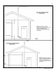
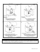
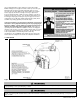
Figure 11 – Horizontal Venting - NOTE: This drawing is meant to demonstrate system venting only. The installer is responsible for all
equipment and detailing required by local codes.
NOTES:
A. For every 1” of overhang, the exhaust vent must be located 1” vertical below overhang (overhang means top of building structure and not two
adjacent walls [corner of building]).
B. Typical installations require 12” minimum separation between bottom of exhaust outlet and top of air intake.
C. Maintain 12” minimum clearance above highest anticipated snow level or grade (whichever is greater).
D. Minimum 12” between vents when installing multiple vents.
E. 12” minimum beyond air intake.
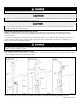
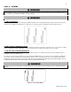
All vent pipes must be glued, properly supported, and the exhaust must be pitched a minimum of ¼” per foot back to the heater to allow
drainage of condensate. When placing support brackets on vent piping, the first bracket must be within 1 foot of the water heater and
the balance at 4 foot intervals on the vent pipe. Heater venting must be readily accessible for visual inspection for the first three feet
from the heater.
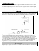
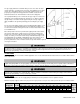
2. VENTING THROUGH AN EXISTING SYSTEM
This heater may be vented through an existing unused vent system. The inner diameter of the existing vent system is utilized for the
combustion air source. Two methods have been approved for such venting: Concentric Venting Through an Existing System and
Venting as a Chase.
VENT / AIR INLET SIZE
MINIMUM EXISTING VENT / CHASE SIZE
2”
4”
3”
5”
4”
7”
Table 8 – Minimum Existing Vent / Chase Sizing