Residential Gas Hybrid Water Heaters Installation Start-Up Maintenance Parts Warranty WGRGH**150 / 199 Models ** “NG” Denotes Natural Gas; “LP” Denotes Propane Gas This manual must only be used by a qualified installer / service technician. Read all instructions in this manual before installing. Perform steps in the given order. Failure to do so could result in substantial property damage, severe personal injury, or death.
WARNING: If the information in these instructions is not followed exactly, a fire or explosion may result causing property damage, personal injury or death. t Do not store or use gasoline or other flammable vapors and liquids in the vicinity of this or any other appliance. WHAT TO DO IF YOU SMELL GAS t Do not try to light any appliance. t Do not touch any electrical switch; do not use any phone in your building. t Immediately call your gas supplier from a neighbor’s phone.
Foreword For the Installer This manual is intended to be used in conjunction with other literature provided with the water heater. This includes all related control information. It is important that this manual, all other documents included in this system, and additional publications including the Code for the Installation of Heat Producing Appliances and National Fuel Gas Code - ANSI Z223.1 (latest versions), be reviewed in their entirety before beginning any work.
Table of Contents Part 1 - General Safety Information A. Operation and Installation Warnings B. Improper Combustion C. Gas D. When Servicing the Water Heating System E. Water Chemistry Requirements F. Freeze Protection G. Water Temperature Adjustment and Scalding H. High Elevation Installations Part 2 - Before You Start A. What’s in the Box B. Optional Equipment Part 3 - Prepare the Water Heater Installation A. Locating the Water Heater B. Leveling C. Clearances for Service Access D.
Vapors from flammable liquids will explode and can cause a fire, resulting in personal injury or death. The water heater has a burner that can come on at any time and ignite vapors. DO NOT use or store flammable liquids around the water heater. Improper venting can cause a build-up of carbon monoxide. Breathing carbon monoxide can result in brain damage or death. DO NOT operate the water heater unless it is properly vented to the outside and has an adequate fresh air supply for safe operation.
This water heater has been designed to heat potable water ONLY. Using this water heater to heat non-potable fluid WILL VOID product warranty, and could result in property damage, personal injury, or death. Do not use this water heater for anything other than its intended purpose (as described in this manual). Doing so could result in property damage and WILL VOID product warranty. B. Improper Combustion Do not obstruct the flow of combustion and ventilating air.
G. Water Temperature Adjustment and Scalding This water heater can deliver scalding water. Be careful whenever using hot water to avoid scalding injury. Certain appliances such as dishwashers and automatic clothes washers may require increased water temperatures. By setting the thermostat on this heater to obtain the increased water temperature required by these appliances you may create the potential for scald injury. H.
Part 2 - Before You Start Open the shipping crate of the water heater. UNCRATING THE WATER HEATER - Any claims for damage or shortage in shipment must be filed immediately against the transportation company by the consignee. A.
Other Optional Equipment Below is a list of other optional equipment available from Westinghouse.
NOTE: When installing in a zero clearance location, it may not be possible to read or view some product labeling. It is recommended to make note of the heater model and serial number. B. Leveling In order for the condensate to properly flow out of the collection system, the area where you locate the heater must be level. Location must also fully support the weight of the filled water heater. D.
Do not attempt to vent this water heater by any means other than those described in this manual. Doing so will void the warranty and may result in severe personal injury or death. Vents must be properly supported. Heater exhaust and intake connections are not designed to carry heavy weight. Vent support brackets must be within 1’ of the heater and the balance at 4’ intervals. Heater must be readily accessible for visual inspection for first 3’ from the water heater.
Products to Avoid Areas Likely to Have Contaminants Spray cans containing fluorocarbons Dry cleaning / laundry areas and establishments Permanent wave solutions Swimming pools Chlorinated waxes / cleaners Metal fabrication plants Chlorine-based swimming pool chemicals Beauty shops Calcium chloride used for thawing Refrigeration repair shops Sodium chloride used for water softening Photo processing plants Refrigerant leaks Auto body shops Paint or varnish removers Plastic manufacturing pl
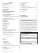
I. Technical Specifications Model 150 199 Installation Indoor, Wall Hung, Fully Condensing Minimum / Maximum Input (Btu/Hr) Hot Water Capacity 15,000 / 150,000 19,900 / 199,000 35oF Rise 8.2 GPM 11 GPM 45oF Rise 6.4 GPM 8.5 GPM 77oF Rise 3.7 GPM Category IV, Sealed Combustion Direct Vent, Power Vent Vent Run 2” (50 feet), 3” (100 feet), Schedule 40 PVC, CPVC, PP Weight (lbs) Orifice Size 5 GPM Flue System 90 100 NG 7.2 mm (0.284”) 8.3 mm (0.327”) LP 5.5 mm (0.217”) 6.2 mm (0.
A B 13.4 5.5 34.2 4.6 4.9 C 15.4 D 29.9 A 10.3 B F 8.8 7.7 E G 3.4 3.1 6.8 10.7 2.8 12.6 15.3 C D E F G 17.3 Figure 3 - 150 Model Dimensions A B 14.8 5.5 C D 36.3 5.7 31.9 11.6 10.6 A 16.8 F 7.20 E B G 2.9 2.6 2.7 6.6 10.5 17.6 C D E F 12.5 G 19.
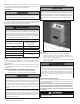
Figure 5 - Components Number Component Description Number Component Description Number Component Description 1 Air Intake Pipe Adapter 14 Condensate Trap 27 Control Panel 2 Flue Air Pressure Sensor 15 Gas Pipe Adapter 28 Heat Exchanger 3 Air Inlet Orifice 16 Condensate Adapter 29 Flame Detection Sensor 4 Air Inlet Pipe 17 Hot Water Adapter 30 Water Level Detection Sensor 5 Gas Outlet Pipe 18 Hot Water Thermistor 31 Main Control Board 6 Burner High Limit Switch 19 C
more or less energy. The negative regulated gas valve provides only the amount of fuel required to ensure clean combustion. The mixer accurately regulates the combination of gas and air throughout the modulating range to ensure high reliability. The burner is constructed of durable ceramic metal fiber for long service life. Water Heater Sensors (Inlet – Outlet – Flue) - Sensors provide highly accurate temperature monitoring to assure accurate system control.
Part 4 - Water Piping t Failure to follow the instructions in this section WILL VOID the warranty and may result in property damage, severe personal injury, or death. DO NOT pipe this water heater with black iron, galvanized steel, steel, or lead pipe. Doing so will result in premature product failure and property damage, and WILL VOID the warranty. Do not apply a torch within 12” of the water heater.
B. Backflow Preventer Use a backflow preventer specifically designed for water heater installations. This valve should be installed on the cold water fill supply line per local codes. C. Potable Expansion Tank A potable hot water expansion tank is required to offset heated water expansion. In most city plumbing systems, the water meter has a no return or back flow device built into the system to prevent back flowing of water into city mains.
RECIRCULATION COLD WATER INLET HOT WATER OUTLET Figure 9 - DHW Piping, Single Water Heater - NOTE: There is a Built-In Flow Check in the Internal Pump Loop NOTES: 1. Minimum pipe size should match connection size. Upsize pipe accordingly if greater flow is required. 2. A thermal expansion tank suitable for potable water must be sized and installed within this piping system between the backflow preventer and the cold water inlet. 3. All circulators should have an integral flow check. 4.
RECIRCULATION COLD WATER INLET HOT WATER OUTLET Figure 10 - Piping with Recirculation - NOTE: There is a Built-In Flow Check in the Internal Recirculation Pump Loop NOTE: For installations where internal pump is not adequate for the recirculation loop, an additional pump can be installed and powered by the appliance (2A Max). See Pressure Drop and Pump Curves, this manual. NOTES: 1. Minimum pipe size should match connection size. Upsize pipe accordingly if greater flow is required. 2.
HOT WATER OUTLET COLD WATER INLET Figure 11 - Water Heater with Storage Tank - NOTE: There is a Built-In Flow Check in the Internal Pump Loop HOT WATER OUTLET COLD WATER INLET Figure 12 - Water Heater with Storage Tank and Recirculation - NOTE: There is a Built-In Flow Check in the Internal Recirculation Pump Loop NOTES: 1. Minimum pipe size should match connection size. Upsize pipe accordingly if greater flow is required. 2.
AIR HANDLER HOT WATER OUTLET COLD WATER INLET Figure 13 - Water Heater with Air Handler without Internal or External Recirculation - NOTE: There is a Built-In Flow Check in the Internal Pump Loop SOLENOID AIR HANDLER HOT WATER OUTLET COLD WATER INLET Figure 14 - Water Heater with Air Handler and Recirculation - NOTE: There is a Built-In Flow Check in the Internal Recirculation Pump Loop NOTE: If Preheat, Internal, or External Recirculation is active when using Air Handler, a solenoid valve must be
COLD WATER INET HOT WATER OUTLET Figure 15 - Water Heater with Thermal Bypass Valve - NOTE: There is a Built-In Flow Check in the Internal Recirculation Pump Loop Using the Optional Crossover (Thermal Bypass) Valve In piping applications where a dedicated recirculation line is not available or too costly to install, the water heater can use a crossover (thermal bypass) valve as a method of recirculation.
AIR SEPARATOR OFF OFF OFF OFF OFF DIFFERENTIAL PRESSURE SPACED TEES WATER HEATER COLD WATER INLET LEAD FREE HOT WATER OUTLET Figure 16 - Water Heater Installed with Combi Appliance - NOTE: There is a Built-In Flow Check in the Internal Recirculation Pump Loop NOTE: The solenoid valve is powered by the water heater. The solenoid valve must be normally closed, energize when the water heater is over 90% of capacity, and deactivate when water heater is less than 50% of capacity.
Figure 17 - Cascaded Water Heaters Figure 18 - Cascaded Water Heaters w/ Recirculation NOTE: For installations where internal pump is not adequate for the recirculation loop, an additional pump can be installed and powered by the appliance (2A Max). See Pressure Drop and Pump Curves, this manual. NOTES: 1. Minimum pipe size should match connection size. Upsize pipe accordingly if greater flow is required. 2.
F. Circulator Sizing Figure 19 - This chart represents the internal recirculation pump performance curve taking into account valves and heat exchanger pressure losses. Figure 20 - This chart represents heat exchanger pressure drop through the heat exchanger and internal valves.
Number of Units ∆T = 77oF Flow Rate (GPM) ∆T = 45oF Water Velocity (ft/s) Pipe Dia. (In.) Flow Rate (GPM) Water Velocity (ft/s) Pipe Dia. (In.) 1 1 5 3.75 3/4 9 3.61 2 10 4.22 1 18 3.21 3 16 4.05 1 1/4 27 4.82 4 21 3.75 35 3.61 5 26 4.69 44 4.52 6 31 3.17 53 3.47 7 36 3.69 8 41 4.22 1 1/2 2 ∆T = 35oF 1 1/2 2 2 1/2 Flow Rate (GPM) Water Velocity (ft/s) 11 4.64 1 23 4.13 1 1/2 34 3.48 45 4.64 57 3.72 68 4.46 62 4.05 80 3.61 71 4.
Part 5 - Venting The heater must be vented as detailed in this section. Ensure exhaust vent and intake piping complies with these instructions regarding vent system. Inspect finished exhaust vent and intake piping thoroughly to ensure all joints are well secured, airtight, and comply with all applicable code requirements, as well as the instructions provided in this manual. Failure to properly install the vent system will result in severe personal injury or death. A.
Due to the extreme flammability of most glues, cements, solvents, and primers used to join plastic exhaust vent and intake pipes, explosive solvent vapors must be cleared from all vent piping before start-up. Avoid using excess cement or primer, as this may pool in the vent pipes. Vent assemblies should be allowed to cure for a period of at least 8 hours before powering a connected appliance.
DO NOT mix components from different venting systems. The vent system could fail, causing leakage of flue products into the living space. Use only the approved pipe and fitting materials, and primer and cement specifically designed for the material used, as listed in the above table. Failure to do so could result in property damage, serious injury, or death. High heat sources (generating heat 100oF / 37oC or greater, such as boiler flue pipes, space heaters, etc.
D. Exhaust Vent and Intake Pipe Location INSIDE CORNER DETAIL G E A H E B B E OPERABLE C FIXED CLOSED FIXED CLOSED D E E I E OPERABLE F M I B E K E E E I B J A K I B L LP-179-CC 03/28/17 E Exhaust Vent Terminal I Intake Pipe Terminal Area Where Intake Terminal Is Not Permitted Figure 22 - Exit Terminals for Direct Vent Systems - ANSI Z223.1 / NFPA 54 for US and CAN/CSA B149.
NOTE: Clean and dry the appliance connection. DO NOT use primer or cement on the appliance connection. 1. The exhaust vent and intake pipe size is 3”. 1. Push the length of pipe into the connection until it touches 2. The total equivalent length of 2” exhaust vent and intake pipe should the bottom of the fitting. not exceed fifty (50) feet; 3” exhaust vent and intake pipe should not 2. Tighten the clamps using a screwdriver. exceed one hundred (100) feet. 3.
11. In vacant chimney applications, install and seal a rain cap over existing chimney openings. 12. All piping must be fully supported. Use pipe hangers at a minimum of 4 foot intervals to prevent sagging of the pipe where condensate may form. 13. Do not use the heater to support any piping. 14. A screened straight coupling is provided with the heater for use as an outside exhaust termination. 15. A screened inlet air tee is provided with the heater to be used as an outside intake termination. 16.
Two Pipe Sidewall Venting with Elbow (Intake) and Coupling (Exhaust) EXTERIOR WALL 1" MIN. 12" MIN.
EXHAUST A AIR INTAKE B FRONT VIEW 24.00 C Exhaust D EXHAUST Intake E AIR INTAKE LP-325-PP 03/31/11 SIDE VIEW F LP-325-OO 02/04/15 Figure 27 - Horizontal (Snorkel) Venting NOTES: A. For every 1” of overhang, the exhaust vent must be located 1” vertical below overhang (overhang means top of building structure and not two adjacent walls [corner of building]). B. Typical installations require 12” minimum separation between bottom of exhaust outlet and top of air intake. C.
2. Venting Through an Existing System This heater may be vented through an existing unused vent system. The inner diameter of the existing vent system is utilized for the combustion air source. Two methods have been approved for such venting: Concentric Venting Through an Existing System and Venting as a Chase. concentric vent kits. Concentric venting through an existing system must run vertically through the roof. See Table 17 for proper minimum vent sizing.
3. Power Venting, Indoor Combustion Air in Confined or Unconfined Space This heater requires fresh, uncontaminated air for safe operation considered part of the space. and must be installed in a mechanical room where there is adequate Confined space is space with volume less than 50 cubic feet per combustion and ventilating air. NOTE: To prevent combustion air 1,000 Btu/hour (4.8 cubic meters per kW) of the total input rating of contamination, see Table 7.