
Use And Care Manual


whl-590 Rev. 003 Rel. 003 Date 3.22.18
40
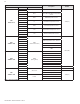
Figure 36 - Wiring Detail
NOTE: T/T only operates when Air Handler Application is selected in
Installer Menu - 19:SU - AH.
Figure 37 - Cascade Wiring Detail
C. Wiring a Cascaded System
When wiring the water heater for Cascade operation, select one
as the Master water heater. The remaining water heaters will be
designated Followers. See “Setting Up a Cascade System” for more
details.
When installing a cascaded system, it is important that the water
heaters are the same model.
Failure to follow these instructions will result in improper system
operation, wasted time, money, and possible property damage
and personal injury. Such damages ARE NOT covered by product
warranty.
Figure 38 - Cable Wired to Board Figure 39 - Installed Resistor
Figure 40 - Title 24 / On Demand Recirculation Wiring Detail
Connect the cascade communication cables to every unit. See
Figure 41. Add resistor to the end of the last follower.
NOTE: The maximum distance between units is two and a half
feet. See Figure 45. This maximum distance can be increased by
connecting additional wire harnesses together. However, the
number of units that can be cascaded will be reduced by one for
every additional harness used.
Every cable comes with one resistor. Use only one resistor on the
cascaded system. Discard the rest.
NOTE: After the cascaded system is set, if you manually turn o the
Cascade Master at the display the entire system will shut down.
NOTE: After the cascaded system is set, DO NOT turn o a Cascade
Follower at the display until you disconnect the cascade cable.
Figure 41 - Maximum Distance Between Wired Cascaded Units