
Instructions / Assembly


14
WHL-004 REV. 5.26.17
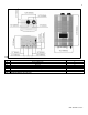
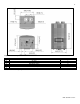
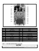
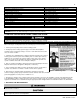
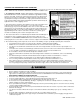
Figure 4 – 199 Model Components
NUMBER
COMPONENT DESCRIPTION
NUMBER
COMPONENT DESCRIPTION
1
Exhaust Vent Adapter
19
Exhaust Duct
2
Air Inlet Pipe
20
Gas Valve
3
AGM (Air Gas Mixer)
21
Gas Inlet Pipe 2
4
Ignition Transformer
22
BLDC Fan
5
Igniter
23
Air Intake Pipe Adapter
6
Flame Detection Sensor
24
Gas Inlet Adapter
7
Primary Heat Exchanger Assembly
25
Freeze Protector
8
Hot Water Outlet
26
DHW Outlet Adapter
9
Mixing Valve
27
Condensate Trap
10
Air Pressure Switch
28
Cold Water Inlet Adapter
11
N/A
29
Cold Water Inlet Filter
12
Manual Power Switch
30
Control Panel
13
Water Adjustment Valve
31
Operating Temperature Sensor
14
Main Controller
32
High Limit Overheat Switch
15
Secondary Heat Exchanger Assembly
33
Ceramic Heater
16
Gas Inlet Pipe 1
34
DHW Sensor
17
Flame Sight Glass
35
Condensate Trap Hose
18
Burner Case
36
Burner Overheat Switch
Table 8 – 199 Model Component List
PART 4 – PREPARE WATER HEATER LOCATION
Carefully consider installation when determining water heater location. Please read the entire manual before attempting installation.
Failure to properly take factors such as water heater venting, piping, condensate removal, and wiring into account before installation
could result in wasted time, money, and possible property damage and personal injury.