
Instructions / Assembly

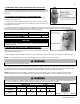


32
WHL-004 REV. 5.26.17
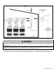
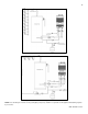
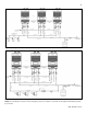
Figure 17 –Common Vented Direct Vent Configurations (199 Model)
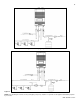
All vent pipes must be glued, properly supported, and the exhaust must be pitched a minimum of ¼” per foot back to the appliance to
allow drainage of condensate. When placing support brackets on vent piping, the first bracket must be within 1 foot of the appliance and
the balance at 4 foot intervals on the vent pipe. Appliance venting must be readily accessible for visual inspection for the first three feet
from the appliance.
For each floor containing bedroom(s), a carbon monoxide detector and alarm shall be placed in the living area outside the bedrooms,
as well as in the mechanical room that houses the heater. Detectors and alarms shall comply with NFPA 720 (latest edition). Failure to
comply with these requirements could result in product damage, severe personal injury, or death.
NOTE: This drawing is meant only to demonstrate system venting. The installer is responsible for all equipment and detailing required by local codes.
For sidewall applications, terminate the outlet on the exterior wall at least 12” above the ground, or as required by local building codes. In areas of high
snowfall, protect both sidewall and roof vent terminations from blockage by installing at least 12” above the maximum anticipated snowfall accumulation.