
Instructions / Assembly


36
WHL-004 REV. 5.26.17
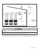
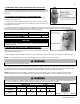
C. ADDITIONAL PRECAUTION FOR EXCESS FLOW VALVE (EFV)
If an excess flow valve (EFV) is in the gas line, check the manufacturer’s minimum
and maximum flow capacity ratings. An improperly sized EFV will not allow for a full
flow of gas to the water heater and will cause the water heater to malfunction. See
Figure 22.
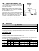
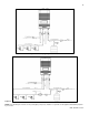
D. ADJUSTING GAS PRESSURE AT THE WATER HEATER
NOTE: Refer Figure 23 when adjusting gas pressure. Loosen the bolts before
checking the gas inlet pressure.
1. The water heater and its individual shutoff valve must be disconnected from the
gas supply piping system during any pressure testing of the system at test pressures
greater than ½ psi (3.5 kPa).
2. The water heater must be isolated from the gas supply piping system by closing its individual manual shutoff valve during any
pressure testing of the gas supply piping system at test pressures equal to or less than ½ psi (3.5 kPa). The minimum and maximum
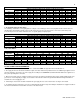
inlet gas line pressures must meet the requirements shown in Table 19.
LP GAS
NATURAL GAS
Minimum Pressure
3.5” WC
Minimum Pressure
3.5” WC
Maximum Pressure
14” WC
Maximum Pressure
14” WC
Table 19 – Gas Pressure Requirements
NOTICE
Do not fire (operate) the water heater until all connections have been completed
and the heat exchanger is filled with water. Doing so will damage the water heater
and void the warranty.
E. SETTING AND VERIFYING THE COMBUSTION SETTING
NOTE: Turn on a hot water faucet at a nearby location in the water heating system to
draw water at a high flow rate. This will ensure the water heater will run continuously
while running the combustion test.
1. After the appliance has fired, flip DIP switch seven (7) to the ON position (low fire). Proceed to check appliance combustion values.
NOTE: Use a combustion analyzer to ensure CO and CO
2
values are within the range shown in Table 20.
It is required to use a combustion analyzer to verify final adjustment according to the combustion chart (Table 20). Failure to do so
could result in serious personal injury or death.
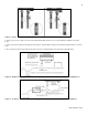
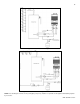
If the readings obtained are lower or higher than the combustion readings in Table 20, use a 4mm Allen key to adjust the offset screw in
a clockwise (positive) or counterclockwise (negative) direction (approximately 1/4 turn). See Figure 24. Check your combustion values.
Repeat this procedure until the values obtained on the combustion analyzer agree with those stated in Table 20.
NOTE: If the appliance makes a whistling sound (harmonics) at low fire, adjust the offset screw in a clockwise (positive) direction
(approximately 1/8 turn). Check your combustion values and ensure they agree with those stated in Table 20 before proceeding.
It is very important that this conversion be set within the recommended CO measurements listed in Table 20. Visually looking at the
burner does not determine combustion quality. Failure to measure combustion with a Combustion Analyzer and set the throttle within
the recommended CO measurements could result in property damage, severe personal injury, or death.
COMBUSTION SETTINGS FOR EFTC-140W
Figure 24 – Gas Valve Offset Screw
NATURAL GAS
LP GAS
FAN SPEED
LOW
HIGH
LOW
HIGH
CO PPM
<60
<200
<60
<200
CO
2
(%)
8 - 10
8 ½ - 10 ½
9 – 10 ½
9 ½ - 10 ½
Table 20 – Combustion Settings
Figure 23 – Inlet Gas Pressure Port Detail
Figure 22 – Excess Flow Valve (EFV)