
Instructions / Assembly


51
WHL-004 REV. 5.26.17
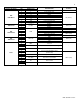
CONNECTOR
DESCRIPTION
HT SELV
NO. OF LOCATION
PIN
BOARD SILK
CN9
65001WS-12
1
-
UNUSED
-
2
L
Power Supply Line
HT (120V~)
3
CP1
UNUSED
4
IT
Ignitor
5
L(HT)
Ceramic Heater (Freeze Protection)
6
GV
Gas Valve
7
EARTH GROUND
8
N
Power Supply Neutral
9-12
AC Power COM Line
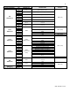
CN1
SMW250-03
1
RS-485
RS485 +
SELV (5V)
2
GND
3
RS485 -
CN4
LWD1140-06
1
FAN
Unused
-
2
GND
SELV (30V)
3
VDD
SELV (14V)
4
Fan power (start coil)
SELV (30V)
5
Fan power (end coil)
6
Fan speed feedback signal
SELV (14V)
CN8
SMW250-04
1
MCU ISP
GND
SELV (5V)
2
ISP / Reset Port
3
ISP TOOL0 Data Port
4
VCC
CN11
1
HWL
Unused
-
8
2
LWL
Water Leak Sensor (150 model only)
10
3
HD
Unused
11
4
TH
Connect to the Display Control
(Thermostat)
SELV (14V)
12
5
Condensate APS
Condensate Air Pressure Switch
13
6
Flue APS
Flue Air Pressure Switch
14
7
BL
Burner Limit
15
8
HL
Water High Limit
16
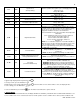
Table 24 – Water Heater Wiring 1