
Instructions / Assembly


whl-004 Rev. 000 Rel. 013 Date 5.1.18
53
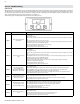
When setting up a cascade system, each individual water heater
control must be programmed for cascade operation.
Program the Master Water Heater:
To program the cascade system, rst enter the Installer Mode. Scroll
down to and select the following parameters on each boiler in the
system:
1. 10:cn – Set the cascade address on the Master water heater
(Master should always be addressed 01) [range from 0-19].
2. 11:Cl – This option dictates the numbers of units that
will operate during every demand (during start-up, it is
recommended to leave 01 [default] to avoid issues with low
ows).
3. 12:Eh - Choose the vent option (ON - Common Vent; OFF -
Individual Vent) - It is very important to choose the proper
settings to avoid safety issues. NOTE: When common vent is
selected, there will be a safety shutdown if one of the units
loses power, or if there is an error with fan and/or control
board.
WARNING: DO NOT attempt to Common Vent 150 model
appliances.
WARNING: DO NOT turn this function OFF when Common
Venting the appliance. Doing so could result in property
damage, serious personal injury, or death.
4. 13:Ct - Choose the total number of units in the cascade
system (if incorrect number of units is selected, Er:78 will
occur).
Program the Follower Water Heaters:
10:Cn – Select the cascade address for each follower (repeat
this step for all followers). Range: 02 - 18.
NOTE: The other settings will be automatically applied to
connected followers after programming the Master.
NOTE: When you set the temperature set point on the Master
appliance it will automatically be applied to the followers.
Master Rotation
• The Master and Followers can rotate or back up each other
in case of error
G. Setting Up a Cascaded System
Common Vented units must be direct vented, with an exhaust vent
and intake air pipe vented to the outdoors. DO NOT power vent
Common Vented units! Doing so will result in property damage,
severe personal injury, or death.
For each oor containing bedroom(s), a carbon monoxide detector
and alarm shall be placed in the living area outside the bedrooms,
as well as in the mechanical room that houses the water heater.
Detectors and alarms shall comply with NFPA 720 (latest edition).
Failure to comply with these requirements could result in product
damage, severe personal injury, or death.
A maximum of eighteen (18) 199 models may be installed in a
cascaded system. A maximum of four (4) 150 models may be
installed in a cascaded system. Installing more than the maximum
amount of water heaters in a cascaded system will result in system
problems, property damage, and premature water heater failure.
Such problems ARE NOT covered by product warranty.
When installing a Common Vented system, it is important that the
water heaters are the same model. Common Venting appliances
of dierent models will result in property damage, severe personal
injury, or death.
Only 199 Model water heaters may be common vented. DO
NOT ATTEMPT to common vent 150 models! Doing so will result
in property damage, severe personal injury, or death.
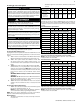
• The Master appliance rotates after a cumulative combustion of
10 hours
Unit 1 Unit 2 Unit 3 Unit 4 Unit 5 Unit 6
Sequence Before
Rotation
CA 01 CA 02 CA 03 CA 04 CA 05 CA 06
Sequence After
Rotation
(10 Hours of
Operation)
CA 06 CA 01 CA 02 CA 03 CA 04 CA 05
Table 31 - Master Rotation - CA - Cascade Address
Follower Rotation
The rst unit to turn on during a DHW demand is the unit that ran
the least amount of time during previous DHW demand. In order for
a follower to rotate it needs to be run at least once (based on burner
on time).
Cascade Transition - Up Transition
Transition 1 2 3 4 5 -
Over Capacity
The control valve reduces the ow when
the load is over 80% of total capacity.
5 to MAX 100% 100% 100% 100% 100%
5 61% 61% 61% 61% 61% !
4-5 76% 76% 76% 76%
4 57% 57% 57% 57% @
3-4 76% 76% 76%
3 51% 51% 51% #
2-3 76% 76%
2 38% 38% *
1-2 76%
1 0%
Table 32 - Cascade Up Transition - * Two units split the previous load in
half, # Three units split the previous load in third, @ Four units split the
previous load in fourth, ! Five units split the previous load in fth
NOTE: If the amount of heat needed to reach 70 - 80% of the total is
needed, another unit comes ON.
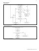
Cascade Transition - Down Transition
Transition 1 2 3 4 5 -
Over Capacity
The control valve reduces the ow when
the load is over 80% of total capacity.
5 to MAX 100% 100% 100% 100% 100%
5 32% 32% 32% 32% 32% !
4-5 40% 40% 40% 40%
4 32% 32% 32% 32% @
3-4 43% 43% 43%
3 32% 32% 32% #
2-3 48% 48%
2 32% 32% *
1-2 64%
1 0%
Table 33 - Cascade Up Transition - * Two units split the previous load in
half, # Three units split the previous load in third, @ Four units split the
previous load in fourth, ! Five units split the previous load in fth
NOTE: If the amount of heat needed to reach 20 - 30% of the total is
needed, another unit comes ON.