California Proposition 65 Warning California Proposition 65 Warning The engine exhaust from this product contains chemicals known to the state of California to cause cancer, birth defects or other reproductive harm. Certain components in this product and its related accessories contain chemicals known to the state of California to cause cancer, birth defects or other reproductive harm. Wash hands after handling.
CONGRATULATIONS ON OWNING A WESTINGHOUSE INVERTER ! DANGER This manual contains important instructions for operating this inverter. For your safety and the safety of others, be sure to read this manual thoroughly before operating the inverter. Failure to properly follow all instructions and precautions can cause you and others to be seriously hurt or killed.
TABLE OF CONTENTS CONGRATULATIONS ON OWNING A WESTINGHOUSE INVERTER..............................................................3 For Your Records: .........................................................................................................................................3 Product Registration .....................................................................................................................................3 Product Registration Form ..........................................
SAFETY SAFETY DEFINITIONS The words DANGER, WARNING, CAUTION and NOTICE are used throughout this manual to highlight important information. Be certain that the meanings of these alerts are known to all who work on or near the equipment. ! This safety alert symbol appears with most safety statements. It means attention, become alert, your safety is involved! Please read and abide by the message that follows the safety alert symbol.
SAFETY GENERAL SAFETY RULES ! WARNING ! DANGER Gasoline and gasoline vapors are extremely flammable and explosive under certain conditions. • Always refuel the inverter outdoors, in a well-ventilated area. • Never remove the fuel cap with the engine running. • Never refuel the inverter while the engine is running. Always turn engine off and allow the inverter to cool before refueling. • Only fill fuel tank with gasoline.
SAFETY SAFETY LABELS The safety labels have specific placement and must be replaced if they are unreadable, damaged or missing.
SAFETY 2 3 1 2 1 3 MWE Investments LLC Columbus OH 43228 USA Designed in Columbus, OH USA Figure 4 8
UNPACKING UNPACKING THE INVERTER ! CAUTION Always have assistance when lifting the inverter. The inverter is heavy; lifting it could cause bodily harm. ! Avoid cutting on or near staples to prevent personal injury. Tools required – box cutter or similar device. 1. Carefully cut the packing tape on top of the carton. 2. Fold back top flaps to reveal the manual. Remove the document and save it for reference. 3. Carefully cut two sides of the carton to remove the inverter.
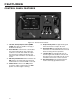
FEATURES CONTROL PANEL FEATURES 3 2 1 7 6 8 5 4 Figure 10 – Control Panel Features 1 - 120-Volt, 20-Amp Duplex Outlet (NEMA 5-20R): The outlet is capable of carrying a maximum of 20 amps. 2 - Reset Breaker: If the inverter is overloaded, the reset breaker will trip. The engine will continue to run, but there will be no output from the inverter. Unplug the devices and reduce the load. Push in the reset breaker to reset it.
OPERATION BEFORE STARTING THE INVERTER Before starting the inverter, review Safety section. Location Selection – Before starting the inverter, avoid exhaust and location hazards by verifying: • You have selected a location to operate the inverter that is outdoors and well ventilated. • You have selected a location with a level and solid surface on which to place the inverter. • You have selected a location that is at least 6 feet (1.8 m) away from any building, other equipment or combustible material.
OPERATION Using Extension Cords – West n se t e e assumes no responsibility for the content within this table. The use of this table is the responsibility of the user only. This table is intended for reference only. The results produced by using this table are not guaranteed to be correct or applicable in all situations as the type and construction of cords are highly variable. Always check with local regulations and a licensed electrician prior to installing or connecting an electrical appliance.
OPERATION 2. Start one of the inverters and wait until the ready light is on. 3. Turn both cord switches to ON (I). 4. Start the remaining inverter; wait until the ready light is on before connecting the load. 5. When power is present, a light will illuminate in the three-prong plug that is plugged into the inverter. INITIAL OIL FILL NOTICE Engine oil must be added when the inverter is on a flat, level surface, or an inaccurate reading may result. Do not overfill.
OPERATION 3. Using the supplied oil fill container and oil, fill the container to the 2.0 mark on the container. Do not overfill (see Figure 23). 2.0 1.5 1.0 0.5 Figure 23 – Oil Fill Container NOTICE Do not tilt the inverter to add oil. It must be filled on a flat, level surface. 4. Add the 200 ml of oil to the engine (see Figure 24). Figure 24 – Adding Engine Oil 5. Fill the container with oil again to the 2.0 mark. 6. Add the 200 ml of oil to the engine.
OPERATION ADDING / CHECKING ENGINE FLUIDS AND FUEL Before adding/checking engine fluids and fuel, review Safety section. Adding Gasoline to the Fuel Tank ! WARNING Never refuel the inverter while the engine is running. Always turn the engine off and allow the inverter to cool before refueling. ! DANGER Filling the fuel tank with gasoline while the inverter is running can cause gasoline to leak and come in contact with hot surfaces that can ignite the gasoline.
OPERATION ! CAUTION ! Avoid prolonged skin contact with gasoline. Avoid prolonged breathing of gasoline vapors. STARTING THE INVERTER For proper starting and operation of the inverter, make sure you review the inverter features and their descriptions. Before starting the inverter, review Safety Section. Before attempting to start the inverter, verify the following: NOTICE The engine is equipped with a low oil shutdown switch.
OPERATION 3. Pull the choke knob out to the ON position (see Figure 29). Using Efficiency Mode The inverter is equipped with an efficiency mode switch to minimize fuel consumption. In efficiency mode, the inverter will sense the load and adjust the engine RPM to the current load requirements. Efficiency mode should be used only after the inverter has been warmed up to operating temperature. 1. To turn on the efficiency mode, press the switch to the ON position (see Figure 31). Figure 29 – Choke Knob 4.
OPERATION STOPPING THE INVERTER Normal Operation During normal operation, use the following steps to stop your inverter: 1. Remove any connected loads from the control panel receptacles. 2. Allow the inverter to run at “no load” to reduce and stabilize engine and alternator temperatures. 3. Move the engine control switch to the OFF position. 4. Turn the fuel tank vent to the OFF position.
MAINTENANCE MAINTENANCE ! CAUTION Before performing maintenance on the inverter, review Safety section and the following safety messages. Avoid skin contact with engine oil or gasoline. Prolonged skin contact with engine oil or gasoline can be harmful. Frequent and prolonged contact with engine oil may cause skin cancer. Take protective measures and wear protective clothing and equipment. Wash all exposed skin with soap and water.
ENGINE OIL MAINTENANCE Engine Oil Specification 1. Only use the engine oil specified in Figure 32. 2. Only use 4-stroke/cycle engine oil. NEVER USE 2-STROKE/CYCLE OIL. Synthetic oil is an acceptable substitute for conventional oil. 0°C SAE 5W-30 25°C SAE 10W-30 A Engine oil must always be checked and added when the inverter is on a flat, level surface, or an inaccurate reading may result, causing serious engine damage. 7. Check oil level: When checking the engine oil, remove the oil fill/ drain plug.
MAINTENANCE Changing Engine Oil Cleaning the Air Filter 1. Stop the engine. The air filter must be cleaned after every 50 hours of use or 3 months (frequency should be increased if inverter is operated in a dusty environment). 2. Let engine sit and cool for several minutes (allow crankcase pressure to equalize). 3. Remove the engine service panel to gain access to the oil fill/drain plug. 1. Turn off the inverter and let it cool for several minutes if running. 4.
MAINTENANCE 5. Wash the foam air filter element by submerging the element in a solution of household detergent soap and warm water. Slowly squeeze the foam to thoroughly clean. NOTICE NEVER twist or tear the foam air filter element during cleaning or drying. Only apply slow but firm squeezing action. 6. Rinse in clean water by submerging the air filter element in fresh water and applying a slow squeezing action.
MAINTENANCE NOTICE Never apply any side load or move the spark plug laterally when removing the spark plug. Applying a side load or moving the spark plug laterally may crack and damage the spark plug boot. 8. Inspect the spark plug for: • Cracked or chipped insulator • Excessive wear • Spark plug gap of 0.032 in. (0.80 mm) (see Figure 51). If the spark plug fails any one of the conditions listed above, replace the plug. NOTICE Only use the recommended spark plug (Torch A5RTC or equivalent).
MAINTENANCE CLEANING THE SPARK ARRESTOR Check and clean the spark arrestor after every 100 hours of use or 6 months. 1. Stop the inverter and let it cool for several minutes if running. 2. Move the inverter to a flat, level surface. 3. Remove the four screws holding the muffler cover in place (see Figure 52). 6. Pull the spark arrestor screen off the muffler exhaust pipe. 7. Using a wire brush, remove any dirt and debris that may have collected on the spark arrestor screen. 8.
MAINTENANCE 5. Insert a feeler gauge between the rocker arm and the push rod and check for clearance (see Figure 54). See Table 2 for valve lash specifications. 3 1 CLEANING THE INVERTER It is important to inspect and clean the inverter before every use. Clean All Engine Air Inlet and Outlet Ports – Make sure all engine air inlet and outlet ports are clean of any dirt and debris to ensure the engine does not run hot.
MAINTENANCE Service Parts 3 4 5 27 2 21 22 25 16 17 18 19 6 14 15 7 8 26 20 9 10 13 11 12 Figure 56 26 23
MAINTENANCE Item 27 Description WH# Qty 2 260005 Reset Breaker 1 3 260014 Efficiency Mode Switch 1 4 260021 Choke Cable 1 5 260039 12-volt DC Power Socket 1 6 260020 Recoil Starter 1 7 260019 Spark Plug Cover (Blue) 1 8 260003 A5RTC (Torch) Spark Plug 1 9 260017 Oil Filling Cover (Blue) 1 10 260015 Oil Filler Plug 1 11 260018 Draining Fuel Cover, Carburetor (Blue) 1 12 260026 Rubber Support Feet 4 13 260016 Air Cleaner Element 1 14 260007 Fuel Tank Cap
TROUBLESHOOTING TROUBLESHOOTING ! WARNING Before attempting to service or troubleshoot the inverter, the owner or service technician must first read the owner’s manual and understand and follow all safety instructions. Failure to follow all instructions may result in conditions that can lead to voiding of the EPA certification or product warranty, serious personal injury, property damage or even death. PROBLEM Engine is running, but no electrical output.
MAINTENANCE NOTES
MAINTENANCE NOTES
MAINTENANCE NOTES