
Installation Manual


whl-007 Rev. 1.14.15
11
3. After ensuring there are no leaks within the system, ush the
system to clear any soldering residue. Many soldering uxes
contain Zinc Chloride, which can corrode stainless steel.
Draw at least three
times the volume of the
water heater to properly
ush the system.
4. Initiate a call for hot
water. Ensure each
zone valve or circulator
operates only when
its thermostat calls for
heat. Purge each zone
of air to ensure proper
operation.
5. Set the water
heater to the desired
temperature. Boiler
high limit should be set
at least 20
o
F higher than
the heater temperature.
Set the low limit of the
boiler control at the
minimum setting - this
will call the burner on only to satisfy the tank control.
A water heater temperature setting of 120
o
F is recommended.
However, a lower temperature setting may be required to
comply with local and state codes for normal operation. The
dierential should be set at 10 to 15
o
F. Installation conditions
may require a higher or lower temperature setting. A mixing
valve in conjunction with a high temperature setting may be
used for high demand applications (spas, hot tubs, whirlpools).
6. When the system is completely ushed, purged of air, and
the temperature is set, turn on the boiler. Observe operation.
Ensure the boiler shuts down after the indirect water heater set
point is satised.
1. Fill the water heater by opening the cold water shut-o valve.
Make certain the eld installed drain valve is completely closed.
Purge air from the system by opening a hot water outlet at a
xture in a kitchen or bathroom. When water ows freely from
the outlet, the system is purged.
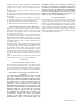
Part 5 - Start-Up and Operation
When lling the water heater, open a hot water tap to release air
in the tank and piping to ensure proper water heater operation.
Failure to ensure the water heater is full before turning on the
system will result in damage to the water heater, and could
result in property damage. Such damages ARE NOT covered
by warranty.
2. Check the system for leaks.
Fix any leaks before continuing the installation. Failure to do so
could result in property damage or personal injury.
Risk of scald injury increases as you increase water
temperature.
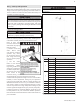
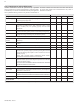
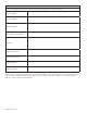
Figure 10 - Replacement Parts
Item # Part # Description
1 6070P-035 Terminal Block w/ Screws
2
6070P-038 Dip Tube Cold Inlet - 30 Gal
6070P-039 Dip Tube Cold Inlet - 40 Gal
7700P-062 Dip Tube Cold Inlet - 50 Gal
6070P-041 Dip Tube Cold Inlet - 60 Gal
6070P-042
Dip Tube Cold Inlet - 80 and 100 Gal
3
6070P-044 Dip Tube Auxiliary Inlet - 30 Gal
6070P-045
Dip Tube Auxiliary Inlet - 40 and 60 Gal
6070P-046 Dip Tube Auxiliary Inlet - 50 Gal
6070P-047 Dip Tube Auxiliary Inlet - 80 Gal
6070P-048 Dip Tube Auxiliary Inlet - 100 Gal
4 TD1012 Thermostat
5 6060P-633 Mounting Clip
6 6060P-634 Protective Cover
7 H3000 Electric Access Panel
8 6075P-006 Screws (#8 Self-Threading)
9 6070P-009 Combination Drain Valve
Table 3 - Replacement Parts List