Sentinel Installation Manual May 2011 Manual Part Number: WG-(TBD) (Ver.
WARRANTY DISCLAIMER WG Security Products Inc. makes no representation or warranty with respect to the contents hereof and specifically disclaims any implied warranties of merchantability or fitness for any particular purpose. Further, WG Security Products Inc. reserves the right to revise this publication and make changes from time to time in the content hereof without obligation of WG Security Products Inc. to notify any person of such revision or changes. WG SECURITY PRODUCTS INC.
TABLE OF CONTENTS OVERVIEW ................................................................................................................................................... 1 SENTINEL OVERVIEW................................................................................................................................... 1 SPECIFICATIONS ........................................................................................................................................ 1 RAD & TAG DESCRIPTIONS ......
Sentinel Installation Manual OVERVIEW Sentinel Overview Sentinel represents the most advanced Asset Protection System on the market today. Sentinel is the perfect fit for applications requiring protection of critical assets, be they items for retail, research, or other property. Additional applications include protection of individuals in assisted living establishments, infants in hospitals, incarcerated people, etc.
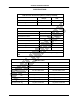
Sentinel Installation Manual SPECIFICATIONS RAD Detection Performance (Master, Auxiliary and EAS) RAD Field Distance Europe USA Up to 20 m Up to 65 ft 120º 120º RAD Cone Angle Electromechanical Specifications Europe USA Field/EAS RAD Dimensions 155x155x60mm 6”x6”2.4” POS RAD Dimensions 200x120x47mm 7.9”x4.7”x1.9” Field/EAS RAD Weights 0.343 Kg 0.76 lb EAS RAD Weight 0.388 Kg 0.86 lb POS RAD Weight 0.678 Kg 1.
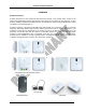
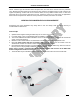
Sentinel Installation Manual RAD & TAG DESCRIPTIONS Field RAD Field RADs are the readers installed in the room over the area to be protected. It radiates the area outward with an approximate 120º cone with strength adjustment range of up to 20 meters (65 feet). And it can be mounted on ceilings to cover an area below its conical beam or on walls to point to a direction and cover a conical space as well. Area Field is dependent on the height of the ceiling and signal strength.
Sentinel Installation Manual alarms. Sentinel tags will self-alarm when tampered with, and also when removed from the protection zone. Bringing the article back into the protection zone quiets the tag without having to take it back to the register for quieting. Sentinel will tie into external alarms, be they audible and/or visual, to alert store personnel that a tag has been detected at the exit. Sentinel is perfect for a wide variety of applications where assets need protection.
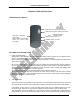
Sentinel Installation Manual TUNING & USER INSTRUCTION Handheld Remote Buttons Up Arrow (Increase RAD Signal Power) Down Arrow (Decrease RAD Signal Power) CON button – EAS RAD Alarm switch – Switch between internal alarm buzzer and external alarm relay switch ARM OFF button - Pause ALM RSE button - Resume Field RAD and EAS RAD Tuning 1. Power Up all field RADs Apply power to all field RADs.
Sentinel Installation Manual alarming, then it means RAD has increased its radiation and field range to cover the location where tag located. Vise versa, if tag doesn’t alarm even tester bring tag two more meters away from the protected area boundary, then it means the RAD has too big of field and coverage is too big. Operator can decrease the RAD’s radiation and field range.
Sentinel Installation Manual Tag and POS RAD Operation Once the Sentinel system has been set up and tuned, the only remaining function is to attach Sentinel tags to the articles and arming them. This section describes the steps in controlling the tags and other features to assist in maintain control over the protected area. The Mode Switch selects between arming and disarming a Sentinel tag as indicated by the left and right indicators.
Sentinel Installation Manual 4. EAS Alarm If the tag enters the field of the EAS RAD, the tag will self-alarm and emit its own coded-signal to the EAS RAD that is typically connected to an external alarm or other device. Notice: by remote control CON button, user can switch EAS RAD alarming between internal alarm buzzer and external alarm relay to external alarm device. During this alarm condition the tag LED will flash at a fast rate. At normal armed status, tag will flash one time per second.
Sentinel Installation Manual Important Notes 1. Keep in consistence with AC24v wiring order when powering all fields RAD, and connect all Field RADs to one dedicated power source. 2. If using WG SPS-24 unit, don’t connect the grounding wire to power supply unit at AC input side. (refer to Dual Backup 24vac Powers Connection Diagram session) 3. If tag pin is not inserted, POS RAD will not able to arm, disarm and disalarm the tag. 4.
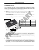
Sentinel Installation Manual RAD’s DIP Switch Configuration On each RAD, there is a DIP switch which can setup the RAD with different configurations. Each Field RAD can be configured with different synchronization ID from 1 to 9. the settings are illustrated as below. EAS RAD has only one setting. Please don’t change the DIP.
Sentinel Installation Manual POS RAD has five settings. The settings are illustrated as below: POS RAD five setting types Functions Descriptions POS RAD-USB Arm, Disarm, Disalarm the sentinel tags, and PC USB connection. If connected to PC, all operations on POS RAD are controlled by PC software; the switch button is invalid then. But LED is still active. POS RAD-All function Arm, Disarm, Disalarm the sentinel tags. The switch button is for switching among the three operation modes.
Sentinel Installation Manual Dual Backup 24vac Powers Connection Diagram This connection diagram provides the connection guidance to use one AC power relay, two 24vac power supplies (WG SPS-24 or customer’s own 24vac power supplies) and one UPS to construct as a dual backup power supply systems which provides more stability to overall power supplies for sentinel.
Federal Communication Commission Interference Statement This equipment has been tested and found to comply with the limits for a Class B digital device, pursuant to Part 15 of the FCC Rules. These limits are designed to provide reasonable protection against harmful interference in a residential installation. This equipment generates, uses and can radiate radio frequency energy and, if not installed and used in accordance with the instructions, may cause harmful interference to radio communications.