58Khz TM Premier Guard Installation Manual Version: Jan 2006 Manual Part Number: WG-PGTR58-IM (011306A) WG SECURITY PRODUCTS INC. 3031 Tisch Way, Suite 602, San Jose, CA 95128 (USA) http://www.wgspi.
WARRANTY DISCLAIMER WG Security Products Inc. makes no representation or warranty with respect to the contents hereof and specifically disclaims any implied warranties of merchantability or fitness for any particular purpose. Further, WG Security Products Inc. reserves the right to revise this publication and make changes from time to time in the content hereof without obligation of WG Security Products Inc. to notify any person of such revision or changes.
TABLE OF CONTENTS OVERVIEW .............................................................................................................................1 SYSTEM OVERVIEW ................................................................................................................1 SYSTEM CONFIGURATION .......................................................................................................2 PREMIER GUARD FEATURES & BENEFITS.....................................................................
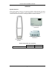
Premier Guard Installation Manual OVERVIEW System Overview Premier Guard systems consist of one a transceiver pedestal, a 58Khz Premier Line Control Unit (WGPLCU58), and a stepdown power transformer box. The PLCU provides all the control functions for the transceiver, including tag detection and alarm notification. Premier Line Control Unit WGPLCU58 24vac Stepdown Transformer WGPS2490-1 Transceiver Antenna (Pedestal) Detection Range (either side of pedestal) Micro Pencil Tag 1 Europe USA 0.
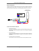
Premier Guard Installation Manual System Configuration The PLCU controls the transceiver through the TX control cable. All detection information is received through the RX cable. The Transformer power box powers the PLCU and transceiver through two separate cables. The following diagram illustrates the connections.
Premier Guard Installation Manual Specifications Electrical Primary Input (Stepdown Transformer) 230/115 ±10% @50/60Hz (Input) 24vac @ 4A (Output) Pedestal Input 24vac @50/60Hz PLCU Input 24vac @50/60Hz Primary Rated Current 0.55Amax@220vac Pedestal Rated Current 1.8A @ 24vac PLCU Rated Current 0.5A @ 24vac Transmitter Output 1.6ms Burst Operating Frequency 58Khz 1.1A max@110vac Mechanical Premier Guard Pedestal Transceiver Height 1523.6mm (60”) Width 374.5mm (14.8”) Thickness 24mm (1.
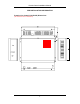
Premier Guard Installation Manual PRE-INSTALLATION INFORMATION Premier Line Control Unit (PLCU) Dimensions (All dimensions are in millimeters) 4
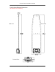
Premier Guard Installation Manual Premier Guard Pedestal Dimensions (All dimensions are in millimeters) Front View Side View Pedestal Base 5
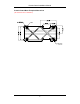
Premier Guard Installation Manual Premier Guard Base Footprint Dimensions (All dimensions are in millimeters) 4-R6 6
Premier Guard Installation Manual Connection Diagram LAN Buzzer Alarm & IR Remote Control Display 24vac Input Channel 2 Channel 1 Fuseholder RX-C&D RX-A&B TX Control Sockets External Alarm Relay RX Sockets 3-Pin Power Connector (1) RX Connectors (1) TX Connector (1) 24vac Power Cable 110/220vac 24vac Transformer RX Cable TX Control 24vac Power Cable 7
Premier Guard Installation Manual INSTALLATION Installation Site Power Supply Verification It is STRONGLY RECOMMENDED THAT SOLID GROUNDING BE MAINTAINED FOR THE POWER TRANSFORMER. Sometimes poor grounding and high noise from the power source will adversely affect system sensitivity or detection range. Parts List –Premier Guard System Control Box WGPLCU58 Transceiver WGPGTR58 Remote Control WG-(TBD) 24vac Transformer WGPS2490-1 Part Name Order Number 1. Premier Guard Transceiver WGPGTR58 2.
Premier Guard Installation Manual Quick Start for System Connections A Premier Guard system consists of a stepdown transformer, a Premier Line Control Unit (PLCU) and a transceiver (antenna). The transformer box has two 24vac outputs that can power both the PLCU and transceiver. A single transformer box supports one PLCU and transceiver. The PLCU is powered by the stepdown transformer via a single 24vac power input. The PLCU has two types of connections for the transceiver.
Premier Guard Installation Manual Transformer Box The transformer box accepts two input voltages: 110vac in North America, 220vac in Europe. Place the Voltage Switch in the proper position based on the incoming voltage (see picture below). There are two 24vac outputs that can power both the PLCU and transceiver. Caution: The Voltage Switch is used to set the system for the appropriate AC input. North America – Set the switch to 115. Europe – Set the switch to 230.
Premier Guard Installation Manual Installing the PLCU The PLCU has one TX Control Signal connector and four RX Signal connectors. Connection to the transceiver is described in the following sections. The PLCU can be installed on the wall via the integrated mounting bracket. To mount the PLCU to the wall: 1. Using the mounting bracket as a template, mark four holes on the wall at the location you intend to install it. 2. Drill holes into the wall and insert anchors or screws.
Premier Guard Installation Manual Connecting the Pedestal Before the connecting the transceiver, place it at the location where you intend to install it, and arrange the cables directly from the PLCU to the transceiver. 1. Remove the base cover of the pedestal to expose the transmitter board (picture below). Note: Press down the top of base cover towards pedestal and LIFT the half case upward to release the cover from the pedestal’s locking mechanism. 2.
Premier Guard Installation Manual (All dimensions are in millimeters.) Top View of Pedestal Plexiglas Antenna Transmitter Board Cable Inlet Slot Note: To direct cables through the inlet slot, first unscrew the cable wires from the connectors and lead the cables through the slot. Then re-attach the wires onto the connector, following the correct pin mappings noted on the connection tables in the next few pages.
Premier Guard Installation Manual Cable and Connector Connections 1. Pedestal and Transformer Box Power Connection The three pins from the transformer power connecter are connected to the corresponding pedestal connector sockets. Pin color to each power connecters must be consistent.
Premier Guard Installation Manual 2.
Premier Guard Installation Manual 3.
Premier Guard Installation Manual 4.
Premier Guard Installation Manual Power Cord Notices North American Power Supply Cords This equipment is supplied with an external power line at one end and a molded receptacle terminal block at the other end. Conductors are color coded white (neutral), black (line) and green or green/yellow (ground). Operation of this equipment at voltages exceeding 130vac will require power supply cords that comply with NEMA configurations.
Premier Guard Installation Manual External Relay interface The external relay interface is located at the side of the control unit case. RxA RxB External Relay RxC RxD Tx Control Valid output terminals To remote alarm Suggested Relay Ratings 1A@250vac/24vdc There is one external alarm relay located on the PLCU case. The relay switch is closed when an alarm is triggered by the system.
Premier Guard Installation Manual Fuse Replacement Information The fuse holder is located on the control box side panel. 1. Equipment shall be electrically disconnected from the branchcircuit supply when replacing the fuse. 2. Remove the fuse holder with a screwdriver, rotating it in a counterclockwise direction. 3. Replace the fuse in accordance with the specification noted below. Power 24Vac Counterclockwise Fuse Fuse Replacement: Extended Fuse (Time-Delay Fuse) 5mm x 20mm 24vac @ T3.
Premier Guard Installation Manual Control Unit Fuse Replacement Transmitter Board – Top View Primary Input Fuse Fuse Replacement: Slow Blow Fuse SMT Type 24vac @ T3A/250V Fuse WARNING – TO REDUCE THE RISK OF DAMAGE, REPLACE ONLY WITH THE SAME FUSE TYPE AND RATING.
Premier Guard Installation Manual Power Supply Fuse Replacement Transformer Case Rear View 1. Equipment shall be electrically disconnected from the branch circuit supply when replacing the fuse. 2. Remove the fuseholder from the main AC input socket with pliers, then remove the fuse out of the fuseholder. 3. Replace the fuse in accordance with the specifications noted below, then insert the fuseholder back into the AC input socket.
Premier Guard Installation Manual IR Remote Control Keypad Description PSW 1 2 3 4 5 6 7 8 9 PC CON 0 TX OFF DFT MIN1 GN SYN ARM OFF MIN2 RE NSE ARM RST SA Key ID Button A GN B SYN C RE H1 MIN H2 EX Parameters Description Default Value Valid Range Gain Adjustment 1 0, 1 Sync Adjustment 1 0 to 250 Receiving Window Delay 8 0 to 14 40 0 to 999 (Practical range 0-200) Noise Display (4 channels) 0 0 to 2 Turn off transmitter 1 0 to 1 0 0 to 1 689 (see note)
Premier Guard Installation Manual Tuning Procedures & Tips There are mainly two problems that affect system’s functioning and performance. One is that system picks up tags and labels poorly. The other is that system false alarms (or causes other system to do so) without tags or labels in detection zone. PROBLEMS SOLUTIONS Interference with or by other systems Low Pick up Rate 1. Check noise “D” (ranging from 0999, >100 or so is big noise & >400 is heavy noise). 2.
Premier Guard Installation Manual Remote Control Programming Without receiving remote control signals, the panel displays the alarm count, indicating the number of times the system has alarmed. See Figure 1. 1 0 Figure 1. Alarm Count Press [PSW] button to open the remote control, then enter the password. The default password, if not previously changed, is 689. 0 Figure 2. Display after [PSW] is Pressed Input Password 689 and press [CON] to confirm/accept the password.
Premier Guard Installation Manual Note: Inputting the wrong password will cause an error message to be displayed as per the following picture. After three successive times of inputting an incorrect password, the remote will be disabled. You will need to turn system power off/on and input the password again. 0 E r r When the correct password is verified, the panel will display the following and is now ready for receiving configuration inputs.
Premier Guard Installation Manual Key ID A: Gain Adjustment (Range: 0-1) • Press [GN] – panel displays as per Figure 3. • Input parameter number. • Press [CON] to accept the parameter. A 1 Figure 3. Key ID B: Sync Adjustment (Range: 0-250; increment: 1) This sets the time from zero crossing point to the start point of transmitting burst. It is important to eliminate crosstalk between different systems. Setting the default value to b-1 will in most cases not interfere with other AM products.
Premier Guard Installation Manual Key ID C: Receiving Window Delay (Range: 0-14; increment: 1) You can input a number from 1-14. The larger the number, the later the receiving window will be opened. • Press [RE] – panel displays as per Figure 5. • Input the parameter number. • Press [CON] to accept the parameter. C 4 Figure 5. Key ID D: Noise Condition Display (Range: 0-4) There are 6 noise level channels displaying different noise types from the two antenna channels. The noise value range is 0 to 999.
Premier Guard Installation Manual Noise Condition Display Configuration Table Value 0 Function Description Detection Purpose Shut down tag or noise window display. D1 Tag window display for channel one. Detect tag entering vertically. D2 Tag window display for channel two. Detect tag entering horizontally. D3 Average noise window display for channel one. D4 Average noise window display for channel two. Monitor average noise.
Premier Guard Installation Manual After confirmation of H1 or H2 values, the panel will display the average noise level weighted by the minimum signal adjustment for both antenna channels as follows. (See NSE noise display entry. It’s the same value with D3, D4) D3 reflects the average noise level weighted by H1 (MIN1) in antenna channel 1. D4 reflects the average noise value weighted by H2 (MIN2) in antenna channel 2.
Premier Guard Installation Manual Key ID E: Load Default Settings (Default value: 0; valid range: 0-1) Value Action 0 Initial state. 1 Load default settings. Input 1 will load default settings. See Default Parameters Table. Key ID P: Password Change (Default value: 689; valid range: 0-999) You can input customer-defined passwords with this entry. Press [CON] button after inputting to activate the new password. Note: Please SAFEGUARD the new password if you have changed from the default.
Premier Guard Installation Manual 32
Premier Guard Installation Manual Addendum 1 Pedestal Sensitivity Adjustment Guide 1. Two Methods to Adjust Sensitivity There are two ways to adjust system sensitivity, and each method has a different effect on the system. A. Handheld Remote – Change the value of H (Minimum Signal Adjustment) at the PLCU using the handheld remote (Ref pages 27). B. POT Adjustment – Tune the antenna coils by adjusting the potentiometers on the transmitter board located inside the pedestal base (Ref page 12).
Premier Guard Installation Manual POT 1 POT 2 Antenna Socket 1 Antenna Socket 2 The tuning POTs only affect a single pedestal. Depending on the specific model of Premier or Plus Line product, the specific POT (1 or 2) will affect a different antenna coil set: a. POT 1 corresponds to the Figure-8 Coil (vertical orientation) and POT 2 corresponds to the Loop Coil (horizontal orientation); -- or -b. POT 1 corresponds to the Loop Coil and POT 2 corresponds to the Figure-8 Coil. c.