
Installation Manual


Wifi StealthPad Installation Manual
8
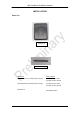
Deactivator Components and Connections
As shown in Figure 1, the deactivator consists of a detect/deactivator antenna pad, power and
control box. The cables used and connections are shown in the following diagram. The
antenna pad can be installed flush to the counter.
HIGH VOLTAGE – HANDLE WITH CARE!
Equipment must be electrically disconnected from
the branch-circuit supply when connecting Wifi
StealthPad
Wifi StealthPad
Always match the antenna type (read the
label on the plastic housing) with control
box input voltage type before connecting
them; make sure they are matched.
Power Plug