PROFESSIONAL SOUND SYSTEMS Titan™ Series OPERATING MANUAL AND USER GUIDE Titan™ 8 Passive Titan™ 12 Passive Titan™ 15 Passive Titan™ 8 Active MKII Titan™ 12 Active Titan™ 15 Active Titan™ Sub A12 Titan™ Sub A15 www.wharfedalepro.
OPERATING MANUAL AND USER GUIDE IMPORTANT WARNINGS & SAFETY INSTRUCTIONS - GENERAL 1. Please read and retain these safety instructions. 2. Heed all warnings in the operating instructions and on the appliance. 3. Do not use this apparatus near water or moisture. 4. Clean only with a dry cloth. 5. Do not install near sources of heat such as radiators, heat registers, stoves or other apparatus that produce heat. 6. Refer all servicing to authorised personnel. 7.
Titan™ Series IMPORTANT SAFETY INFORMATION POWERED PRODUCTS exposed to dripping and splashing and no object filled with liquids such as a vase of flowers should be placed on the product. No naked flame sources such as candles should be placed on the product. Caution: Changes or modifications not expressly approved by the manufacturer could void the user's authority to operate this device.
OPERATING MANUAL AND USER GUIDE TABLE OF CONTENTS 1……………………………..Important Warnings & Safety Instructions 2……………………………..Important Safety Information Powered Products 4……………………………..Introduction / About the Titan™ Series 5……………………….…….Titan series overview 6……………………….…….Features 7……………………………..Setting up / Speaker Placement 7……………….…………….Connections / Wiring - Passive 8……………….…………….Rear Panel Layout - Passive 8……………….…………….Connection Diagram Passive 11……………….…………….Rear Panel Layout - Active 14…………..……………..….
Titan™ Series INTRODUCTION Wharfedale Pro Titan™ Series are the result of many years of experience in the use, design and manufacturing of professional loudspeaker products. We take great pride in engineering and building every Wharfedale Pro loudspeaker and wish to thank you for entrusting us with your sound. From the time Gilbert Briggs built his first loudspeaker in 1932, to the present, Wharfedale Loudspeakers have maintained the same standard of quality in components, workmanship and performance.
OPERATING MANUAL AND USER GUIDE TITAN™ SERIES OVERVIEW The Titan Series are powerful, accurate, high quality loudspeaker systems with low distortion that are designed to deliver high quality sound at a cost effective price point. The road tough polypropylene enclosures are ultra lightweight and include rubberized handles and cable channeling to keep wiring neat and tidy. Comprehensive rigging options suit the Titan series to flown applications and a range of wall mount options.
Titan™ Series Titan Passive ♦ Bi-amplified full range loudspeakers ♦ Moisture proof woofers ♦ HF compression drivers ♦ Independent LF & HF signal limiting ♦ Per channel volume controls (Master only on 8A) ♦ 2 Band EQ ♦ 90° x 60° elliptical Wave Guide (EWG) ♦ BRO™ Bass Response Optimizer (12A & 15A only) ♦ Horn LED defeat switch (8A only) ♦ XLR output for parallel wiring ♦ XLR / ¼” jack combo inputs ♦ Mic / line level input selector ♦ 2 mixable inputs (12A & 15A only) ♦ Stereo RCA
OPERATING MANUAL AND USER GUIDE SETTING UP 1. Ensure the speakers power switch is in the off position (Active models only) 2. Set the level controls to minimum (Fully anticlockwise) (Active models only) 3. Set the EQ controls to 0dB (Active models only) 4. Select mic/line input (Active models only) 5. Connect all signal cables 6. Connect the power cable (Active models only) 7. Switch on source equipment, ensuring that the master level is at minimum 8. Switch on the Titan Loudspeaker (Active models only) 9.
Titan™ Series TM Titan™ REAR PANEL LAYOUT INPUT: +1 Positive -1 Negative PARALLELINPUTS POWER HANDLING: 150 W atts C ontinuous 300 W atts Program 500 W atts Peak Im pedance: 8 O hm s WWW.WHARFEDALEPRO.COM INPUT: +1 Positive -1Negative : POWER HANDLING 200 Watts Continuous 500 Watts Program 1000 Watts Peak Impedance: 8 Ohms WWW.WHARFEDALEPRO.
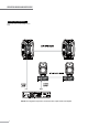
OPERATING MANUAL AND USER GUIDE CONNECTION DIAGRAM # 2 Titan mono front of house+stage monitor setup Left Right NOTE: This configuration represents a 4 ohm load to each output channel of the amplifie 9
Titan™ Series CONNECTION DIAGRAM # 3 USING THE Titan WITH A PASSIVE SUBWOOFER CONNECTION DIAGRAM # 4 USING THE Titan™ 8/12/15 IN A BI-AMP SYSTEM 10
OPERATING MANUAL AND USER GUIDE Titan™ 8 / Titan™ 12 / Titan™ 15 ACTIVE The Loop / Mix Switch The LOOP/MIX switch allows you to control the signal content going to the XLR OUTPUT jack. In the “LOOP” mode, this switch routes the signal of INPUT B to the line level XLR OUTPUT jack, bypassing the EQ section and volume control. When in the MIX mode, this switch routes the combined (or “mixed”) signals of both INPUT A and INPUT B to the line level XLR OUTPUT jack.
Titan™ Series Titan™ 12/15 ACTIVE REAR PANEL LAYOUT Heat Sink 2 HI / LOW EQ (equalization) controls 4 VOLUME control A&B l MA X 6 RCA INPUT L & R (Left and Right) 8 MIC / LINE switch 0 l MA X 0 OFF HIG H ON POWER ON LED indicator and LIMIT LED indicator 3 POWER ON / OFF switch 5 “BRO™” circuit switch 7 OUTPUT source LOOP / MIX switch 9 POWER connector 11 XLR OUTPUT connector 12 LOW -1 0 d B G A IN CD/TAPE 10 +10dB -1 0 d B 1 LO O P +10dB MI X XLR / ¼" combo jacks fo
OPERATING MANUAL AND USER GUIDE TITAN™ 8/12/15 ACTIVE REAR PANEL FEATURES 1. Heat Sink: The heat sink allows for dissipation of heat built up from the amplifier via air cooling at the rear of the enclosure. 2. HI and LOW EQ (equalization) controls: These knobs control the equalization of the overall output signal providing +/- 10dB of gain for each band. 3.
Titan™ Series Titan™12A / 15A CONNECTION DIAGRAM # 1 Basic microphone / playback hookup MP3 Player 0 HI 0 0 ON - +6 ∞ VOLUME - MA X ∞ VOLUME +6MA X -12dB -10dB LOW +12dB +10dB POWER 0 L OFF HIGH INPUT LOW -12dB -10dB R GAIN O FF LIM IT +12dB +10dB EQ CD/TAPE B AS S RES PO N SE ON OPTIMIZER Place switch down in “MIX” position AC INPUT MI X LOO P AC Power Cord A (BALANCED) AC220-240V~60Hz AC220-240V~50Hz 400W FUSE T4AL 250V (BALANCED) B INPUT INPUT INPUT OUTPUT to
OPERATING MANUAL AND USER GUIDE TITAN™ SUB A12 REAR PANEL FEATURES 1. HEAT SINK Cooling fins for amplifier. Do not obstruct. 2. VOLUME CONTROL Adjusts the volume. 3. INPUT L Balanced line level input via a XLR/ ¼” combo connector. 4. INPUT R Balanced line level input via a XLR/ ¼” combo connector. 5. OUTPUT R Balanced male XLR connector provides output HIGHPASS signal. 6. OUTPUT L Balanced male XLR connector provides output HIGHPASS signal. 7.
Titan™ Series Titan™ Sub-A12 CONNECTION DIAGRAM # 1 TWO CHANNEL SYSTEM WITH HIGHPASS OUTPUT 120 H z 150 H z 100 H z 180 H z 200 H z 80 H z 0 180 M AX LOW PASS FILTER L ( BAL/UNBA L) ( BALANCE D) R INPUT OUTPUT AC220 240V 50Hz 250W FUSE T3.
OPERATING MANUAL AND USER GUIDE Titan™ Sub-A12 CONNECTION DIAGRAM # 2 USING TWO Titan™ Sub-A12 WITH TWO POWER SPEAKERS 120Hz 150Hz 100Hz 180Hz 200Hz 80Hz 0 180 M A X LOW PASS FILTER L (B A L /U N B A L ) (B A L A N C E D ) INPUT OUTPUT R AC220 240V 50Hz 250W FUSE T3.15AL250V 120Hz 150Hz 100Hz 180Hz 200Hz 80Hz 0 180 M A X LOW PASS FILTER L (B A L /U N B A L ) (B A L A N C E D ) INPUT OUTPUT R 17 AC220 240V 50Hz 250W FUSE T3.
Titan™ Series Titan™ Sub-A15 - REAR PANEL FEATURES 1. INPUT A - Balanced line level input via a XLR / ¼” combo connection. 2. OUTPUT A - Balanced male XLR connection provides “THRU” or HIGHPASS signal (depending on switch setting). 3. SPEAKER LEVEL INPUT - Allows for connection of an external amplifier to use the Titan™ Sub-A15 as a passive subwoofer. NOTE: Disconnect the power cord when using the Titan™ Sub-A15 in this mode. 4. INPUT B - Balanced line level input via a XLR / ¼” combo connection. 5.
OPERATING MANUAL AND USER GUIDE Titan™ Sub-A12 CONNECTION DIAGRAM # 1 TWO CHANNEL SYSTEM WITH HIGHPASS OUTPUT TO LEFT ACTIVE SPEAKER OR AMPLIFIER INPUT TO RIGHT ACTIVE SPEAKER OR AMPLIFIER INPUT INPUT OUTPUT (B A L A N C E D ) (B A L A N C E D ) I 0 I I I I I A I I I I +6 8 _ WWW.WHARFEDALEPRO.
Titan™ Series CONNECTION DIAGRAM # 2 USING TWO Titan™ Sub-A15's WITH TWO POWERED SPEAKERS TO LEFT MAIN POWERED SPEAKER INPUT OUTPUT (B A L AN C E D ) (B A L AN C E D ) I 0 I I I I A I I I MAX 8 _ I I WWW.WHARFEDALEPRO.
OPERATING MANUAL AND USER GUIDE SPECIFICATIONS - Titan™ PASSIVE SERIES Titan™ 8 Titan™ 12 Titan™ 15 Loudspeaker Type: 8" 2-way 12" 2-way 15" 2-way Frequency Response (+/–3dB): 70 - 20kHz 55 - 20kHz 50 - 20kHz Sensitivity (1W@1M): 96dB 98dB 97dB Peak SPL: 124dB 128dB 129dB HF Coverage (H x V): 90˚ x 60˚ 90˚ x 60˚ 90˚ x 60˚ System Impedance: 8 ohm 8 ohm 8 ohm Continuous: 150W 250W 400W Music: 300W 500 800W Peak: 600W 1000 1600W Size: 203mm/ 8" 305mm/ 12" 381mm/ 15"
Titan™ Series SPECIFICATIONS - Titan™ ACTIVE SERIES Titan™ 8 ACTIVE MK II Titan™ 12 ACTIVE Titan™ 15 ACTIVE System Type Active 8” 2-way Bi-Amplified Active 12” 2-way Bi -Amplified Active 15” 2-way Bi -Amplified Frequency Response (+/-3dB) 70-20kHz 55-20kHz 50-20kHz Low Frequency Driver (mm/in.) 205mm / 8” 305mm / 12” 381mm / 15” High Frequency Driver Compression Driver Titanium Compression Driver Titanium Compression Driver Exit Size (mm / inches) 30mm / 1.
OPERATING MANUAL AND USER GUIDE SPECIFICATIONS - Titan™ ACTIVE (Con't) Titan™ 8 ACTIVE MKII Titan™ 12 ACTIVE Titan™ 15 ACTIVE Switchable balanced mic or line Switchable balanced mic or line Switchable balanced mic or line level input level input level input Mic: -47dBu (-49.2dBv or Mic: -36dBu (-38.2dBv or Mic: -36dBu (-38.2dBv or 3.4mVrms) 12.28mVrms) 12.28mVrms) Line: 0dBu (-2.2dBv or 0.775Vrms) Line: +4dBu (1.78dBv or Line: +4dBu (1.78dBv or 1.228Vrms) 1.
Titan™ Series SPECIFICATIONS - Titan™ SUB SERIES TITAN™ Sub-A15 Titan™ Sub-A12 System Type Band-pass subwoofer Reflex subwoofer Frequency Response (+/-3dB) 45-150Hz 55-200Hz Enclosure Material 18mm Plywood 15mm MDF Enclosure Colour Grey or Black Grey or Black Frame material Die-cast aluminium frame steel frame Size (mm / inches) 404mm / 15” 305mm / 12” Coil Size (mm / inches) 75 / 3” 64.26mm / 2.
OPERATING MANUAL AND USER GUIDE DIMENSIONS 8.7” 221mm 15.59" 396mm O 10.47” 266mm 8.7” 221mm 12.28” 312mm 21.89” 556mm O 15.11” 384mm 12.
Titan™ Series DIMENSIONS 15 15.83” 402mm 27.87” 708mm O 18.81” 478mm 15.83” 402mm 8.7” 221mm 15.59" 396mm O 10.47” 266mm 8.
OPERATING MANUAL AND USER GUIDE DIMENSIONS 12.28" 312mm 21.88" 556mm O MIX -- ) AA (BALANCED) INPUT _ OPTIMIZER BR O O (BALANCED) OUTPUT 15.11" 384mm 12.28" 312mm 7.1" 180mm 15.83” 402mm 27.87” 708mm 18.81” 478mm 15.
Titan™ Series DIMENSIONS 493.0 431.0 Titan SUB A12 TOP VIEW 360.0 360.0 463.0 120Hz 150Hz 100Hz 180Hz 200Hz 80Hz 0 180 MAX LOW PASS FILTER L (BAL/UNBAL) (BALANCED) INPUT OUTPUT R AC 22 0 240V 50Hz 250W FUSE T3.15 AL 250V 431.0 SIDE VIEW FRONT VIEW Titan REAR VIEW SUB A15 TOP VIEW INPUT (BALANCED) OUTPUT (BALANCED) I 0 I I I I I A I I I WWW.WHARFEDALEPRO.
OPERATING MANUAL AND USER GUIDE WHARFEDALE PRO LIMITED WARRANTY Wharfedale Pro products are warranted of manufacturing or material defects for a period of one year from the original date of purchase. In the event of malfunction, contact your authorized Wharfedale Pro dealer or distributor for information. *Be aware that warranty details may differ from country to country. Contact your dealers or distributor for information. These terms do not infringe your statutory rights.
Wharfedale Professional IAG HOUSE, Sovereign Court, Ermine Business Park Huntingdon, Cambs, PE29 6XU, England www.wharfedalepro.com Wharfedale Professional reserves the right to alter or improve specifications without notice. All rights reserved © 2010 Wharfedale Pro. Wharfedale Pro is a member of the International Audio Group (IAG).